In July 1943, Tiger 250391 was the first to be fitted with the "New turret", creating what we now call "Mid Tigers". It incorporated many design changes, but its electrical wiring was not very different to the wiring in the "Old turret".
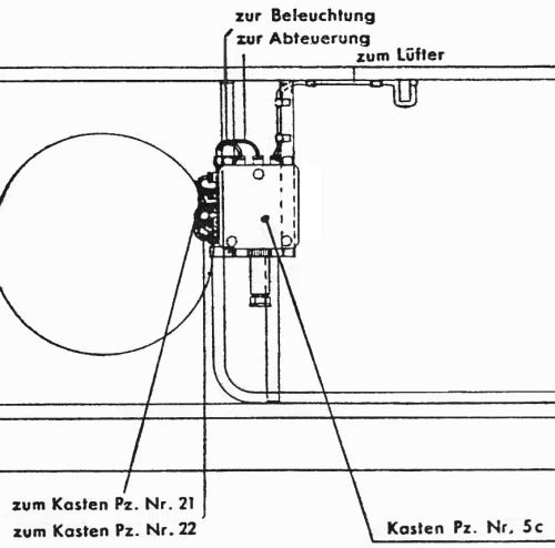
This extract from the Turret Manual [2, see plate 61] shows the "Kasten 5c" junction box in the "New" turret. Most things here are unchanged, with the cables for "Beleuchtung" (lighting), "Abfueurung" (firing) and the intercom cables all going into a sleeve that descends to the turret ring.
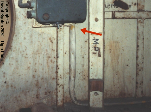
The sleeve is drawn descending from the left edge of the junction box, but in every surviving Tiger it comes from the right-hand edge. This would not be the only case of the factory foreman ignoring the Tiger's design specification because he knew better.
In the drawing, the lead marked "zum Lüfter" (to the ventilator) doesn't run directly to the roof as in an "Early Tiger". The fan in this "New" turret was moved to the center of the roof. Therefore its power lead runs along the top of the wall, ducks underneath a strut, and only then begins to run along the underside of the roof.
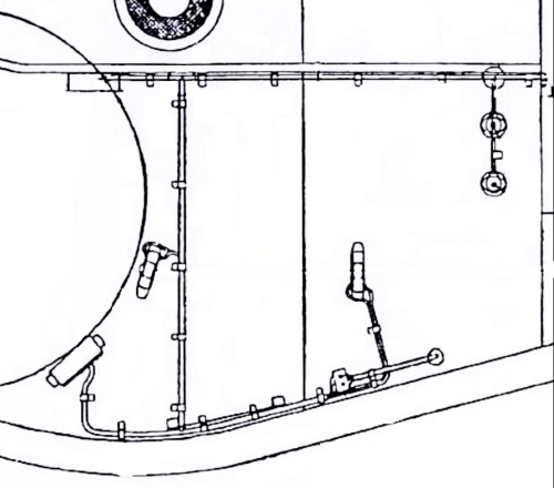
There are no surviving standard "Mid Tigers" in the world today, and precious few internal photos from WW2. We could be grateful that the Turret Manual lays out the complete wiring in the "New" turret, except for one problem : it's partially wrong.
The relevant drawings were obviously completed before the "New" turret design was finalised, and they do not match what was eventually built. For example, in this extract from the Manual, the smoke grenade triggers are drawn [2, see plate 61] . But the smoke system was deleted before the "New" turret was introduced. Most of this wiring never existed in any "Mid Tiger".
I have therefore inferred the "Mid Tiger" turret wiring layout, from a surviving "Mid Befehlstiger" at Kubinka Museum (which has similar but augmented wiring), from the manual's diagrams, and from the prior "Early" and subsequent "Late" turrets.
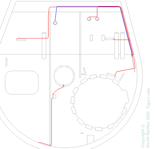
This is the result. The lighting circuit is drawn in red, and the trigger circuit in blue.
The only questionable aspect of the diagram is the fan's power lead, because in the Kubinka tank it does not obey the Turret Manual. It follows the other cables to the circuit board, to the front of the roof and thence to the fan switch. A power lead for a lamp takes its place on the riser from the "Kasten 5c". But that arrangement can be specific to Befehlstigers, whose loader's lamp is at the rear of the roof, displaced by the radio. So I assume that the Turret Manual is correct for standard Tigers.
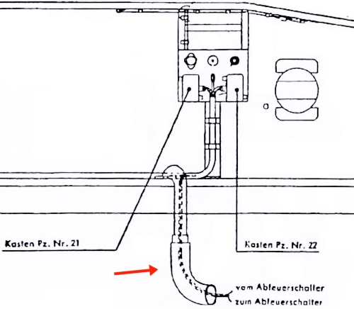
All the other cables arrive beneath the main circuit board via the sleeve running along the turret ring. This extract from the Turret Manual shows that the trigger power lead then makes a detour inside a hollow structural beam (arrowed).
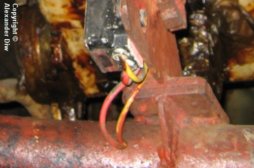
As we can see in the Kubinka vehicle, the trigger power lead emerges from the beam to reach the trigger lamp. The trigger signal lead returns via the same route to rejoin the other cables. All of them are then routed up to the circuit board, where the intercom and lighting cables terminate at the appropriate components.
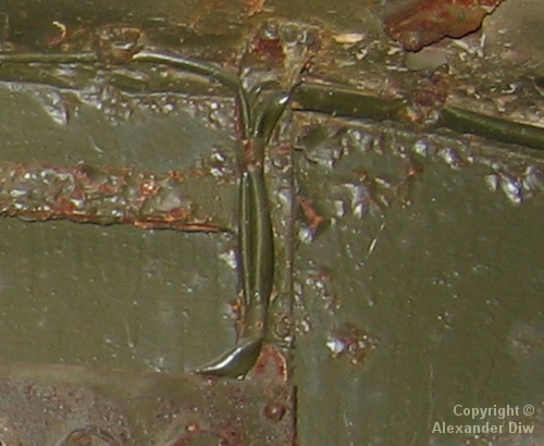
The trigger lead, and the power leads to the various lamps, then go to the roof via the forward leg of the main circuit board. The manual shows them using the rear leg, but photos of a standard "Mid Tiger" and the surviving Kubinka vehicle disagree with the manual on that point.
One of these cables is a power lead that runs rearwards to the commander's lamp. Another single lead goes forward to the gunner's lamp.
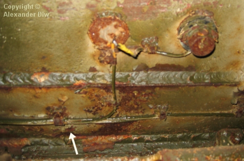
There are three remaining leads, all in a sleeve that ends by the forward left corner of the roof (arrowed). From there the three leads go their own ways, with the telescope lamp lead immediately diverting to the pair of power sockets on the roof (one of them is missing here).
This wiring layout persisted in "Mid" Tigers until around September-October 1943, when the "Kasten 5c" junction box was moved, forcing a change to the wiring.