The Tiger's smoke grenade triggers were originally placed on or near the turret ring. But eventually they were moved to the roof so that the commander could operate them himself. That of course required a change to the "Initial Tiger" turret wiring.
We don't know exactly when this change was made, but likely it was at the 56th turret, when the turret's equipment stowage was thoroughly reworked. The side escape hatch was added at almost the same time, therefore the modified layout is associated with what we call "Early Tigers". Bovington's Tiger "131" is an example.
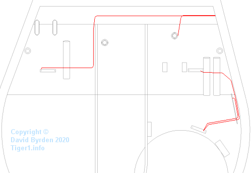
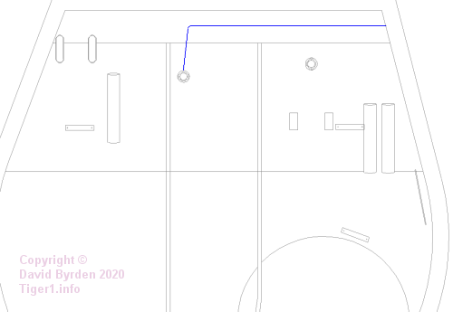
The layout of the lighting circuit wires, shown here, was not affected by this change [2] .
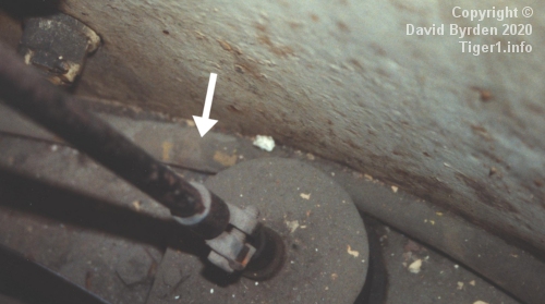
Also unaffected was the main cable sleeve, running from the "Kasten 5c" to the main circuit board. In this photo, the sleeve passes behind the commander's azimuth indicator.
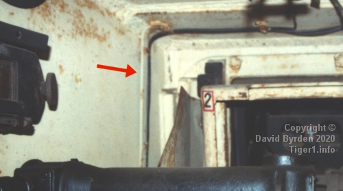
Because of the moved trigger boxes, there was no longer a cable running up the right-hand turret wall. But the cable riser at the left front corner of the turret was unchanged. A sleeve containing three cables was clipped to a welded vertical strip there.
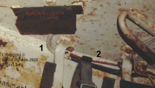
As for the trigger boxes themselves, this one is ahead and to the left of the commander. Three cables connect to it. The thick cable at [1] is actually a sleeve containing three trigger leads for smoke grenades. For most of its length it is black, but it has been painted "Ivory" at this end.
The red lead at [2] is the power line from the junction on the main circuit board. Another cable runs from this trigger box to the other one, chaining the power supply to it. That cable is not easy to see in this photo, but it runs to the metal strip at the right of the photo, then across the roof.
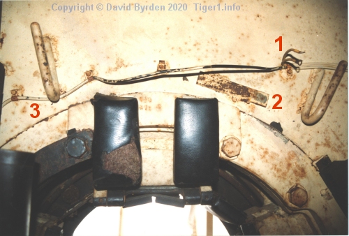
This is the roof immediately in front of the cupola. Leads at [1] for the commander's lamp are detached because the lamp has been removed from this museum tank at [2]. The power line for the right-hand trigger box is at [3].
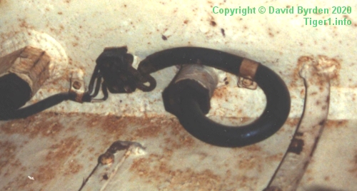
From each external smoke grenade array, a thick water-resistant cable enters the tank via a watertight seal. The three leads from the abovementioned black sleeve are brought out and connected to it via a small junction device.
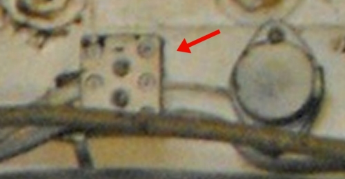
I don't have a good photo of that junction from a Tiger, but here is an identical one in a Panzer IV. It has six screw terminals allowing three pairs of leads to be connected.
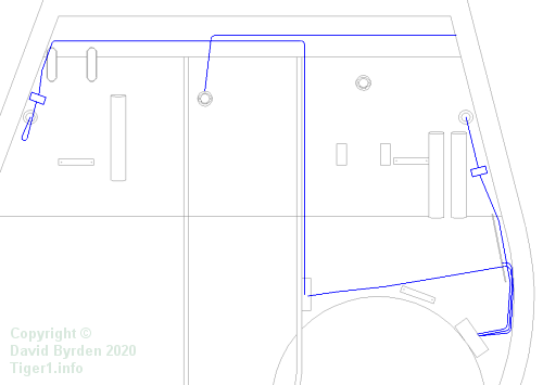
The trigger wiring layout for this turret version is drawn here. The bulk of it, including power leads and trigger cables, is for the smoke grenade system. The trigger boxes are by the cupola at the lower right.
At the 286th turret the smoke launcher system was deleted [1, see 3.4.2.1] . The only remaining trigger wire was for the main gun. The Tiger continued in production with this wiring layout until the introduction of the "new turret".
[1] DW to Tiger 1
[2] Survey of Tiger 250122, at Bovington museum, by David Byrden