Circuit board
At the start of Tiger production, electronics in the tank's turret were bolted to mounts welded to the turret wall. The tank's design was being rapidly refined, however, and somewhere about the 20th vehicle a circuit board was introduced in the turret. Some components that had formerly been on the wall were moved to it. The board stood clear of the wall to protect them from impact shocks.
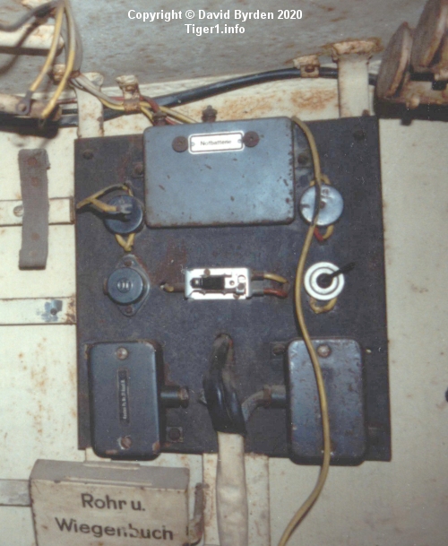
This circuit board is in Tiger "131" at Bovington museum. This is a pre-restoration photo with the original paint and wiring [5] . Only the case of the central switch is missing. The board carries portions of the lighting circuit, the trigger circuit and the intercom circuit. The large item at the top is the backup battery. It is flanked by two junction boxes.
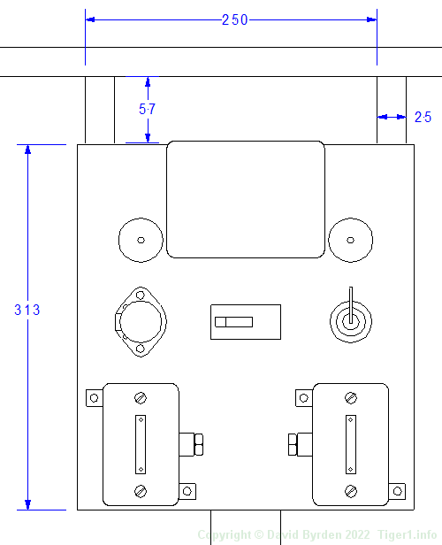
Here are some dimensions of the board. It was attached to a metal frame welded to the turret ring and the roof.
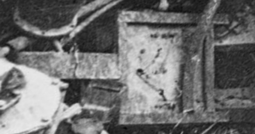
The earliest evidence of this board's existence is from the demolished Tiger "833" in Tunisia. This Tiger is about the 30th from the production line. Extracted from that photo, this distorted image shows the tank's circuit board lying face down in the wreckage. We can see the metal frame and some of the wiring behind it
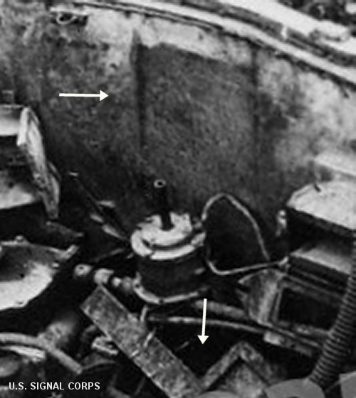
Another photo of the destroyed turret of "833" shows both the board and an unpainted rectangle on the wall where it used to be. This position agrees with the much later Tiger "131".
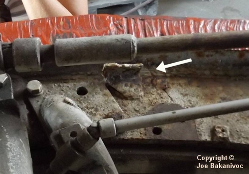
As for the other preserved Tiger from this time, Tiger "712", portions of its walls were cut off and discarded after the war. Its circuit board is gone. However, we can still find this stub where the supporting leg was welded to the turret ring.
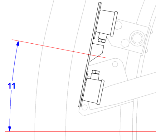
By comparing it to items of known position, we can see that the circuit board was centered 11 degrees forward of 9 o'clock, as shown in this plan view of the left side of the turret.
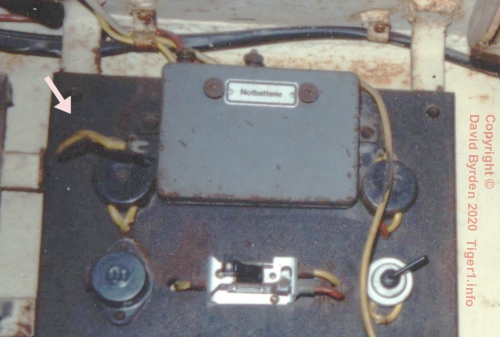
The board in Tiger "131" should be almost identical to the first such boards, with just one visible difference. When the smoke trigger boxes were moved to the roof, they were taken off the main battery and put on the turret's backup battery. This short cable was added, connecting the battery to a junction (in this photo it's detached). It was the only cable placed out in front of the board.
Evolution of the board
The evolution of this board after Tiger "131" and up to the end of the "Early Tiger" period is not clear. There is a German diagram, dated March 1943, where this board is depicted without the backup battery. But certain changes shown in that diagram did not come into production until July (with the "new" turret). Also, the backup battery was powering the smoke grenade system, which is still drawn on that diagram and was not deleted until the 286th turret [4, see 3.4.2.1] . The battery may have been deleted at that time, or perhaps it remained until the "Mid" turret appeared.
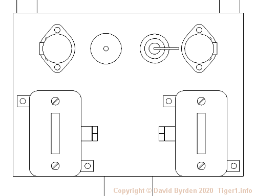
Whenever it happened, the backup battery was eventually deleted and the top portion of the circuit board was cut off. The intercom boxes on the bottom of the board were left alone, but the remaining components were now arranged in a row [3] . A second power socket was added to the board [2, see plate 59] .
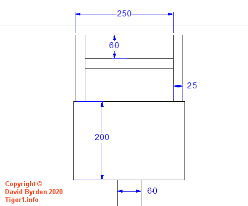
Here are some dimensions of it. The backing metal frame was not changed.
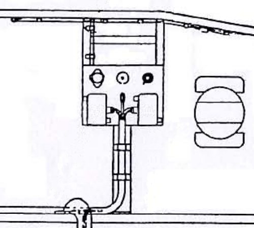
Most of the Tiger's design records have been lost, but there are clues to what happened in the "Early" Tiger. This is part of a diagram in the Turret Manual. It shows the reduced board but with only one power socket [2, see plate 61] . The diagram must have been drawn during the "Early" period because it mixes features of old and new turrets, as if the "Mid" design was incomplete. Did the draftsman draw the board that then existed in "Early" turrets?
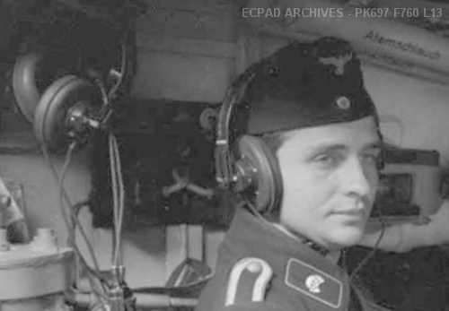
This is inside a Tiger issued about 6 weeks into the "Mid" period. The circuit board is visible in this photo (and others). It has four components, as expected in a "Mid" Tiger, but they are not laid out in a row. Three of them are evenly spaced, but the round metallic switch has been squeezed in between them. This circuit board was obviously drilled for three components, and later modified to carry four. It's a classic example of a part becoming obsolete before it is pulled from the bottom of the stockpile.
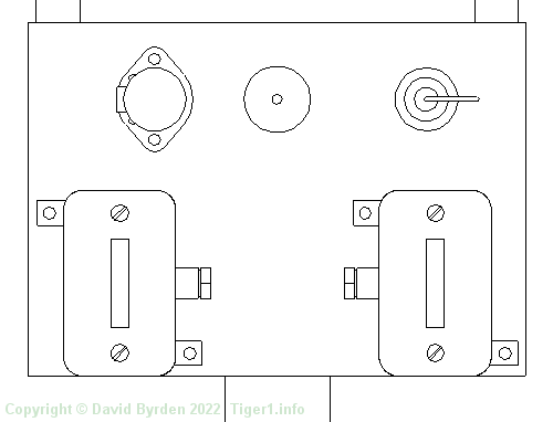
This strongly suggests that the last "Early" Tigers did have a circuit board with three components, as drawn in the manual.
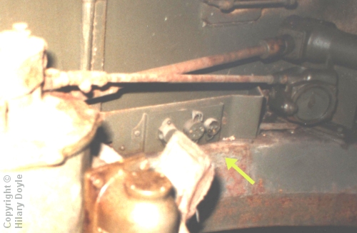
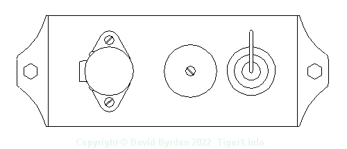
Much later, around October 1943, the turret was simplified to save costs. This standalone circuit board was eliminated and the items from it were moved elsewhere. The intercom socket boxes went to the roof, and the remaining electrical components were put on the small metal panel, attached to an open storage bin beside the gunner. This photo is from a "Late" Tiger. [1]
Command Tigers
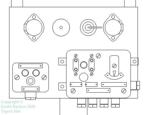
Command Tigers ( "Befehlstiger" ) began production shortly after the circuit board was introduced. Indeed, it was obviously designed to accomodate them. They carried the same size board as the corresponding version of standard Tiger, but substituted their own intercom boxes.
I don't know what was changed in Command Tigers when the turret was simplified in late 1943. But they were so few in number that the designers may never have bothered to rework their "Mid" electronics layout. In that case, a circuit board would have been present in all Command Tigers to the end.
[3] Survey of Tiger at Kubinka museum by Alexander Diw
[4] DW to Tiger 1
[5] Survey of Tiger 250122, at Bovington museum, by David Byrden