In September-October 1943, the Tiger was simplified to speed production and lower cost. This involved a number of changes that affected the "Mid Tiger" turret wiring. We don't know the timing or sequence of the changes, but we know the wiring layout after they finished. It probably remained the same for the rest of Tiger production, being used in the later "Mid Tigers" and all of the "Late Tigers".
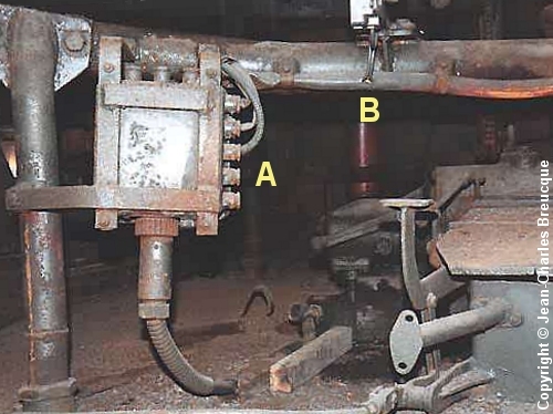
The turret junction box "Kasten 5c" was moved from the rear wall to the forward floor support leg. Here, we are looking backward into the turret [2] . Cables from the junction box at [A] go into a sleeve that runs along a structural beam. The trigger lead emerges from the sleeve at [B], making a detour to the trigger and back.
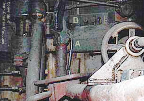
The beam and trigger are at the lower right of this photo. The sleeve runs up, at [A], to the left-hand turret ring. It goes behind the gunner's stowage bin at [B], and then the power lead for the lighting circuit emerges from the sleeve.
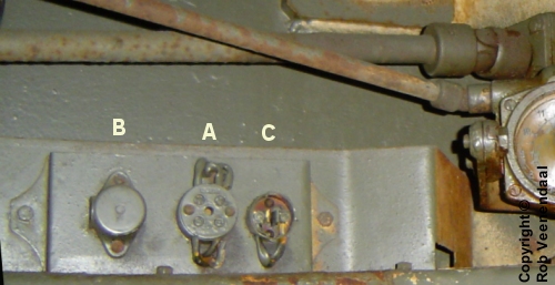
The lead goes to this adjacent circuit board. Fixed to the loader's stowage bin, this small panel replaced the larger circuit board of earlier turret versions [3] .
The power lead ends in the junction box at [A]. This has four screw terminals, but we can count six cables connected to it. Two of them are for the hand-lamp power socket at [B] and the power switch at [C] (this one is damaged). The remaining leads are for the roof lamps, so they return to the wiring sleeve.
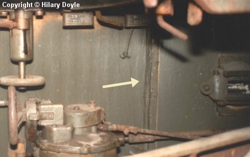
The sleeve then runs up to the roof, clipped to a metal strip. The strip is placed exactly where the support leg of the main circuit board had stood in earlier turret versions [4] .
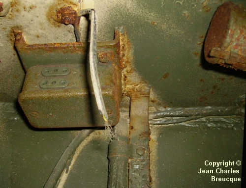
This "Late" Tiger in Saumur museum is not as well preserved as Bovington's "131". Its insides have been painted green. But we can still see some of its original "Ivory" paint, and although lamps etc. are missing and their wires are detached, we can see how they emerge from the top of the sleeve. An intercom box is fixed to a roof bracket at the left, and the power lead for the commander's lamp runs through the bracket. Another lead, and a sleeve containing several more, runs to the right along the edge of the roof.
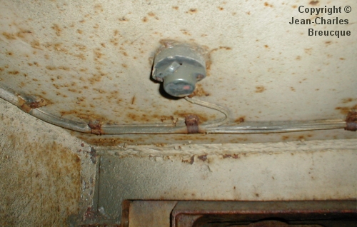
This is the front left corner of the roof. The sleeve contains four leads, and it ends here. One lead immediately goes to the power socket for the telescope's internal lamp. That lead comes from the power switch on the circuit board. One of the design changes to simplify the turret was the elimination of a second socket from here.
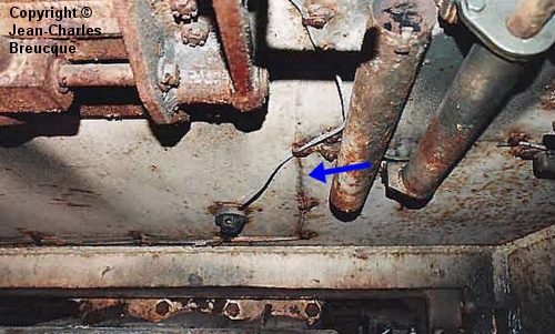
When the Tiger's turret roof was thickened to 40mm, the two struts welded to its underside were deleted. That created an opportunity to reroute the wiring directly across the roof, instead of running it to the front of the turret to get around the struts. But the designers did not make that change. They left the roof wiring exactly where it was.
Here, a mark on the paint (arrowed) shows where a lead was attached when this tank was new. That lead was placed exactly where it had been on the 25mm roof, beside the ghost of a departed roof strut, which itself was a memory of the raised segment in the VK4501(P) roof.
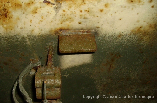
The ventilator fan switch was fixed to this tab welded to the roof.
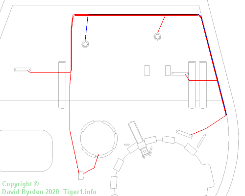
This diagram shows the underside of a 40mm roof. Both the lighting circuit (red) and the trigger circuit (blue) are drawn on it. Not all of the equipment on the roof is shown.
[1] Survey of Tiger 250122, at Bovington museum, by David Byrden
[2] Survey of vehicle 251114, at Saumur, by Jean-Charles Breucque
[3] Survey of Tiger 251114, at Panzermuseum Munster, by Rob Veenendaal