The Tiger 1 was equipped for underwater travel, therefore all joints and openings were sealable. In the original turret design, there was a complex sealing device in the turret ring.

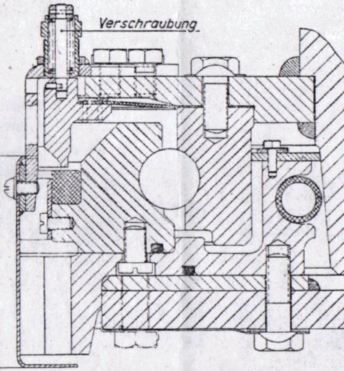
This cross-section of the turret ring shows that water, entering the ring at lower right of the diagram, would have to pass through a labyrinth before reaching the crew compartment at the left. The first barrier was an inflatable rubber tube (the shaded circle). Above that, a dust guard provided scant protection. The water's pressure would push it through the gap in the ball-bearing race, between the ball bearings and relentlessly toward the left of the diagram, where it would encounter one final safeguard.

There was a thick rubber ring mounted on the inner side of the ball-bearing race. This model shows it. Four metal strips, each secured by 7 screws, held the rubber ring in place and exposed its top surface.
Referring back to the cross-sectional diagram, you will see that another steel ring lay immediately above the rubber. To complete the seal, it was necessary to lower this ring onto the rubber and force it down hard. The turret should already be locked and unable to rotate.

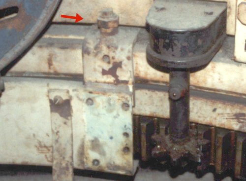
To push down this ring and lock it, the turret ring had nine clamps distributed around it. This photo shows one of them; it is also drawn in the cross-sectional diagram.
By rotating the locking nut (arrowed) you press down on the steel ring immediately below it. The rubber seal is hardly visible here but the flat strip that locks it in place can be seen. Immediately below that are the teeth for the traverse mechanism. We can see these details in this photo only because a segment of the protective cowling has been removed; it attaches to the clamp brackets.

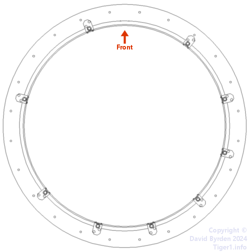
Because of the many items of equipment attached to the turret ring, the locking clamps could not be evenly distributed around it. Here are their positions.
The "New turret" of 1943 didn't have this sealing device. It relied entirely on the inflatable tube to keep water out of the turret ring.