Locking the Early turret
The original Tiger's turret was locked by a plunger, with a mechanism similar to that in the existing Panzers, but much more robust. The lock was in the hull, on the underside of the roof. By pushing down a handle you could raise a plunger up through the roof and into the wall of the turret [3, see page 91] .
The lock
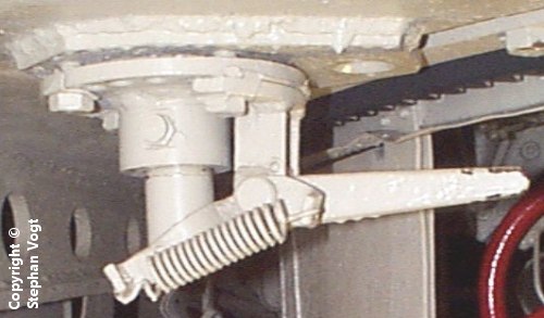
This is the lock, in Tiger "712" before restoration [1] . It has been painted white but was originally black. The plunger is visible at the lower left of the image, and is connected to the end of the handle. The spring holds the plunger in either the raised or lowered position; here, it is lowered.
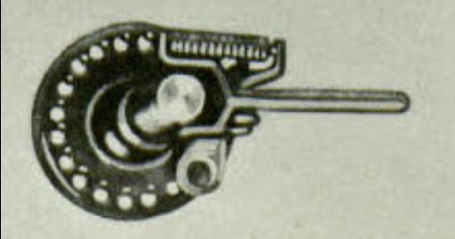
This is the complete lock. It weighs 5.3kg [4, see Tafel 82] .
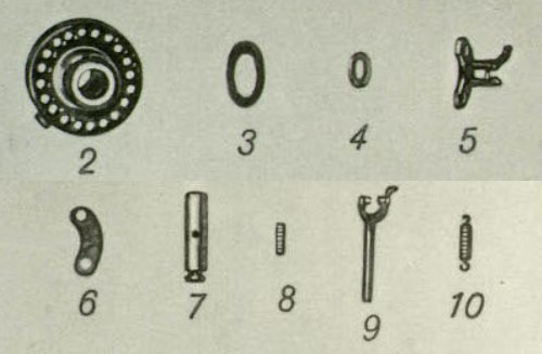
This is how the device breaks down into parts. I don't know why the base plate has so many holes; it is held by only four bolts. The holes allow you to position the oil lubrication tap anywhere around the sleeve, at intervals of 18 degrees, but I can't see why that is important. Perhaps the same lock was used in the Tiger (P) and it needed to be configured for the vehicle it was in?
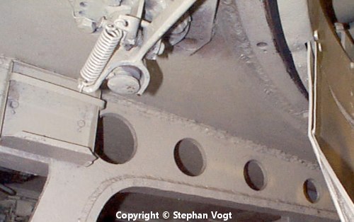
This photo shows where the lock is placed in relation to the forward bulkhead and the turret. The plunger is at exactly 45 degrees left of the turret's axis.
Locked positions
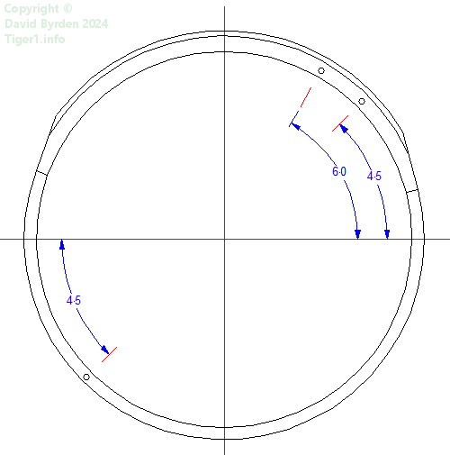
The plunger would enter one of three round holes drilled into the bottom edge of the turret wall. This diagram is a view of the bottom edge, showing their positions. Since the plunger was at 45 degrees left, the turret could be locked facing directly forward, directly backward, or 15 degrees to the left.
The roof plate
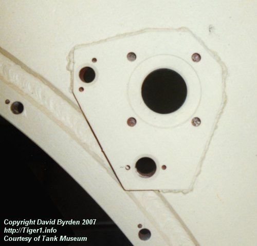
The lock was bolted to a shaped plate that was welded to the roof. There were waterproofing seals at every joint. This is the bare plate in Tiger "131" [2] .
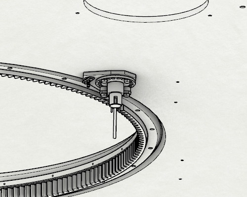
The plate was behind the driver's hatch.
Submersion equipment
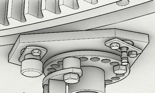
The same welded plate was used for sealing the submersion equipment that protruded into the hull : the drain tube (at our left in the image) and the inflator valve of the main sealing tube. Both of them were made watertight by a rubber ring, pressed against the plate by a metal tab with 2 bolts. It was necessary to unbolt and remove these two seals before lifting the turret off the hull.

Here is the tab and rubber seal for the drain tube [4, see Tafel 83] .

This is the drain tube, its tab, its rubber seal and its screw cap [4, see Tafel 85] .
The second version
During the "Early Tiger" production run, this turret lock was improved. The connection between handle and shaft was changed. The openings in the turret wall were changed from round holes to slots, covered by small welded panels. And the top of the cylindrical plunger was tapered so that it would be easier to find a slot with it.
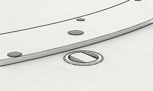
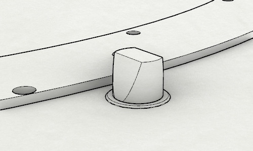
These are the two positions of the tapered plunger.
[1] Survey of Tiger 250031, by Stephan Vogt
[2] Survey of Tiger 250122, at Bovington museum, by David Byrden
[4] Kraftfahrgerät teil 3, Fahrgestell und Turm Panzerkampfwagen "Tiger", heft 60