The ring of teeth
The Tiger's turret had a ring-shaped housing on its lower inside wall that contained its ball-bearing race. The floor of the housing was a flat steel ring that carried the teeth of the rotation gear.
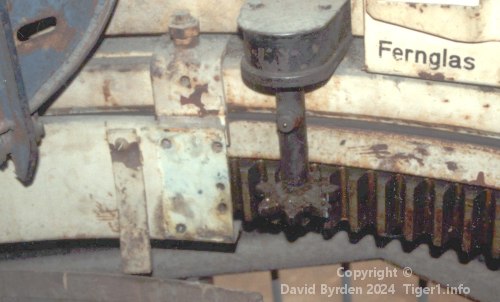
The teeth were not usually visible. Here is a view from inside the turret (this is Tiger "131" being restored in the 1990s [2] ). The teeth are covered by a sheet-metal cowling, but a segment of the cowling has been removed here, exposing the teeth.
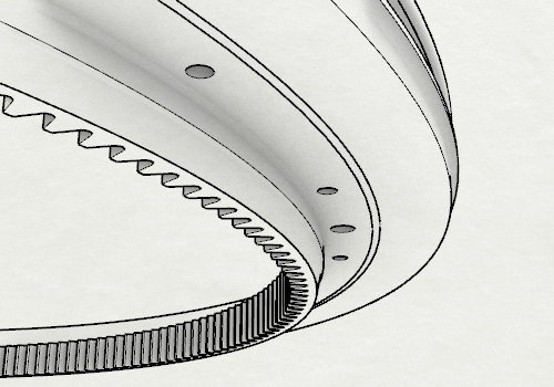
This is the underside of the toothed ring. This surface is visible when the turret is lifted off the tank. The teeth protrude below the level of the turret base and into the hull. The manual states that this ring has 240 teeth [1, see page 9] , but that is an error; it really has 204 [4, see page 89] . A rubber sealing strip is embedded in the ring. The ring weighs 200kg. [5, see Tafel 84]
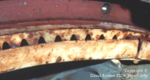
Looking from underneath, we can see only a glimpse of the teeth when the cowling is installed. In this photo, the turret still has its original paint. The ring was painted in red primer during manufacture, and that colour is still present. But when the final "ivory" colour was sprayed inside the assembled tank, it covered the exposed part of the toothed ring.
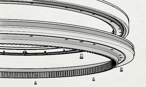
The ball-bearing race was attached directly on top of the toothed ring. Eight screws linked them, as shown here. The toothed ring had eight recessed holes so that these screws would not protrude.
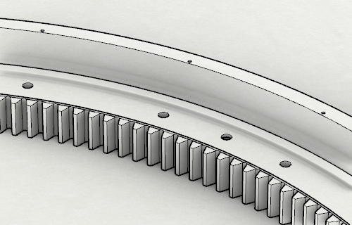
Another twenty-four holes were evenly spaced around the ring so that the turret could be attached to the hull by bolts screwed into the ball-bearing race from below. They were threaded through a seating ring on the hull roof.
A small ridge ran around the toothed ring, just outside the bolt holes, to seat the ball-bearing race. The ring also had a tall outer flange with 24 small screw holes for attaching a dust guard [4, see page 90] .
Submersion equipment
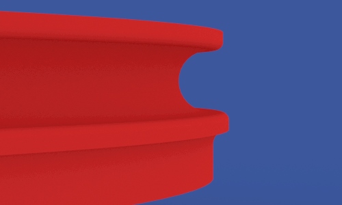
The original Tigers could submerge, therefore many joints in the tank were sealed with rubber. But the rotating turret and the hull did not touch each other except via the ball bearings, so a permanent rubber seal could not be placed between them. Instead there was an inflatable tube. It was placed in this channel, in the outer flange of the toothed ring [4, see page 90] .
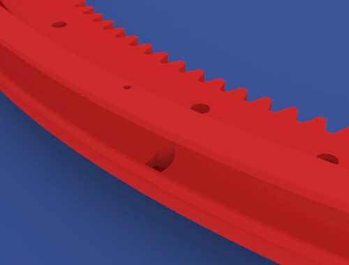
The tube had an inflator valve on a thin tube that ran down through this small hole in the toothed ring, to the crew compartment in the hull.
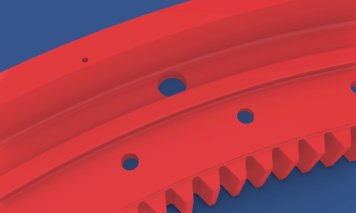
Because water would be trapped in the toothed ring after submersion, it had a single drain hole, again leading to the crew compartment.
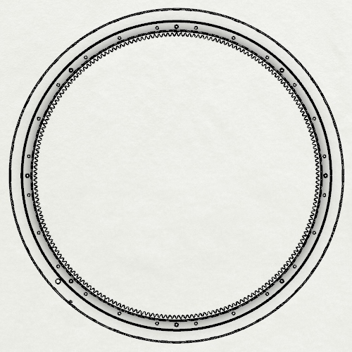
This is a view of the toothed ring from underneath. The drain hole and the inflation hole are close together, at bottom left of the image, which is the forward left quadrant of the ring when installed on the tank.
Additional bolts
Due to reports of Tiger turrets surviving impacts but detaching from their hulls, the number of bolts in the turret-hull joint was doubled, starting with the 201st vehicle [3, see 3.4.2.13] . The new bolts were mostly put between the existing ones at the same radius, to support back-compatibility of turrets and hulls. But four of the 24 new bolts were placed at a larger radius, linking the hull directly to the toothed ring.
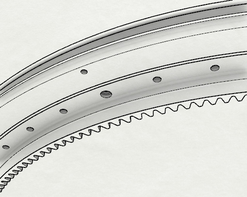
This view of the underside shows additional bolt holes, including one of the outer holes. One of the screws was already in the position it would have taken.
The turret was also improved by the addition of two pins to guide it while being lowered onto a hull. These two pins were screwed into the toothed ring, which therefore gained two more holes. One of them was beside the submersion equipment, an already crowded area of the ring.
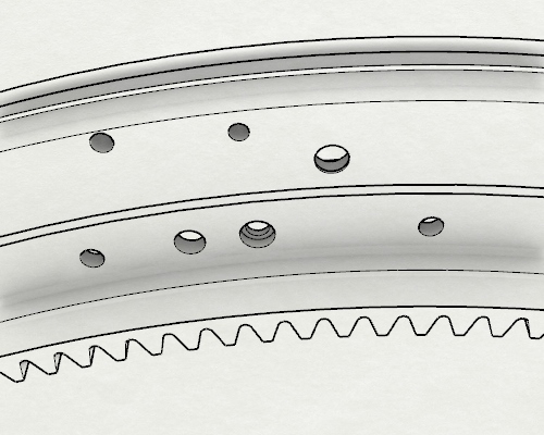
We are looking at that area from below: the hole at top left is for the inflator valve, the large hole to its right is for the drain, and between them is one of the four displaced bolt holes; but this one also attaches the turret lock. On the inner circle, the hole for a guide pin is the one that's not evenly spaced.
The third version
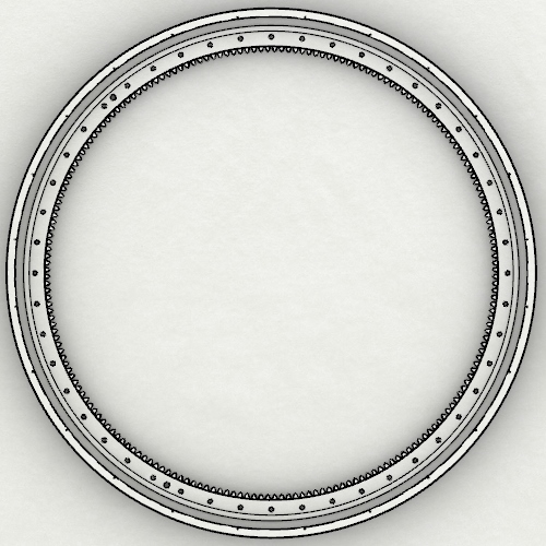
Submersion equipment was deleted from the Tiger's design in the autumn of 1943. For the toothed ring, that meant the elimination of the drain hole, the inflator hole and the large outer channel. In this plan view, you can see that the drain hole is gone. The sequence of evenly spaced holes is broken only by the two threaded holes for guide pins.
Profile of the toothed ring
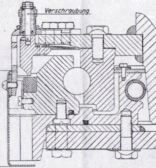
This cross-section of the turret ring and hull roof was extracted from a manual [1, see plate 8] . The toothed ring is shown here, with the hull roof below it and the ball-bearing race above. The teeth are at lower left, the turret's outer wall is at extreme right, and the inflatable tube is the circle touching that wall.
[2] Survey of Tiger 250122, at Bovington museum, by David Byrden
[3] Germany's Tiger Tanks, volume 1 : DW to Tiger 1
[5] Kraftfahrgerät teil 3, Fahrgestell und Turm Panzerkampfwagen "Tiger", heft 60