The turret seating ring
Like other Panzers, the Tiger had a flat, carefully machined ring welded to its hull roof, where the turret would sit. One benefit of such a ring is that it's easier to drill and precisely shape the plain steel ring than the armour plate of the roof.
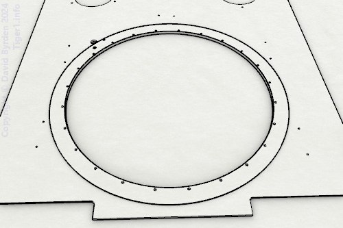
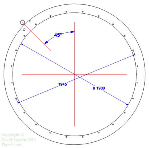
Here are some dimensions of the seating ring [1] . To the forward left of the ring there is a hole in the roof plate, for the turret lock.
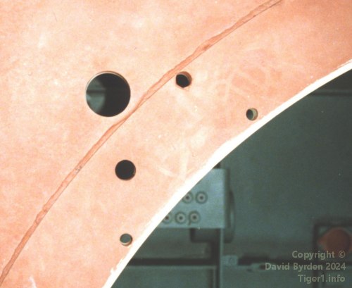
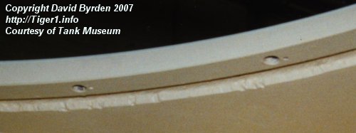
This is the forward left corner of the seating ring on the Tank Museum's Tiger "131" [1] . The photo was taken during restoration of that vehicle. The two additional holes in the seating ring are for the turret ring drain and for the inflator valve of the sealing tube [4, see plate 8] .
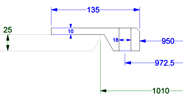
This is a section through the seating ring at the site of a bolt hole. The hull roof plate is specified to be at least 25mm thick. Note that the bolt holes don't pass through the roof plate. [2] [1]
This photo, taken from within the hull, shows the bottom of the ring and two of the bolt holes.
Additional bolt holes
The Tiger had a design flaw in that the bolts attaching the turret to the hull were a weak point. They could break when the turret was hit by otherwise survivable AP rounds. The first solution was to replace them by stronger bolts. Later, starting with the 201st turret, the number of bolts was doubled [3, see 3.4.2.13] .
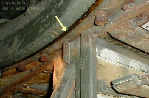
For the sake of back-compatibility with existing vehicles, the original 24 bolt holes were retained and the new bolts were put between them. But not all of the 24 new positions could be used. The four quadrant positions were blocked by equipment inside the hull, such as this ammunition bin at 3 o'clock.
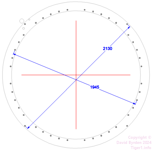
Another four positions were blocked by the fixing screws of the toothed ring in the turret. Therefore, bolt holes at those angles were placed near to the ring's outer edge. The bolt at front left was shared with the turret lock. There were now 44 bolts fixing turret to hull (the manual mistakenly says 48 [4, see page 9] ). This diagram highlights all of the bolt positions, new and old.
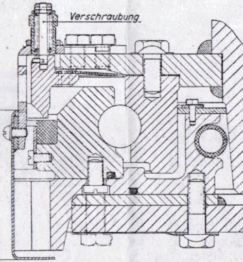
This German diagram is a cross-section of the ring and the turret mechanisms that sit upon it [4, see plate 8] . (The ring is represented as flat without a deep rim on the inside; this is an error. Refer back to my diagram for the true profile.) An original bolt position is drawn at lower left, and one of the new outer bolts is at lower right. The screw in the toothed ring that displaced it is also drawn.
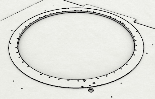
This view of the modified seating ring shows the 44 bolt holes, and the two holes for submersion equipment. There are also two new, larger holes in among the bolt holes; one of them near to us, and the other one at upper right of the image. These two new holes are for locating pins.
Locating pins
The turret was difficult to align when being replaced on the hull. Therefore another improvement was made; two locating pins ("Einbaudorn") were added to the turret bottom, and holes for them were made in the seating ring [4] . This feature was added during or after April 1943, possibly at the same time as the extra bolts; it was certainly present by the 236th hull. The same pins were used on the Tiger B.
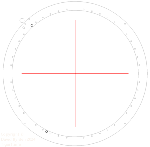
This diagram highlights the holes for the locating pins. At 30mm diameter, they were slightly larger than the bolt holes; it would, of course, be undesirable for the locating pins to fit in the bolt holes.
The Tiger B's locating pins were placed centrally fore and aft. These positions were not available on the Tiger E because of structures within its hull.

This is a diagram of a pin. I don't know if these pins were carried permanently in the Tigers; they may have been kept by the workshops and applied only when needed.
The New Turret
The "New Turret" introduced in July 1943 brought more changes. It had a new turret lock, so the hole in the roof adjacent to the seating ring was presumably no longer made [3, see 3.4.2.20] . When the desigers eliminated the old lock, they apparently erased the bolt that it shared with the seating ring, leaving only 43 [5] .
Another improvement was the addition of robust steel washers to all 40 of the inner bolts. The idea was that if the turret was struck, the washers would deform and absorb the shock (the bolts should be tightened up afterwards). The idea was a success; photographs prove that when these new turrets were torn off by explosions, the ring would break open at the ball bearings rather than at the bolts.
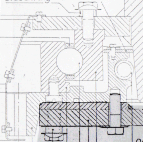
This diagram from the Turret Manual is a cross section of the ring in the "New Turret". Washers have been added to the main sequence of bolts (at lower left) and also to the bolts on top of the mechanism [4, see plate 9] .
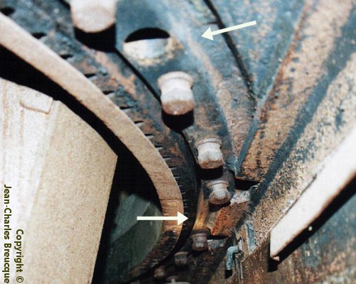
This photo was taken in the Saumur museum vehicle, just behind the commander's seat [5] . You can see that the turret fixing bolts have washers. I have pointed out the hole for the rear locating pin, and the unused bolt position at 6 o'clock.
Final version
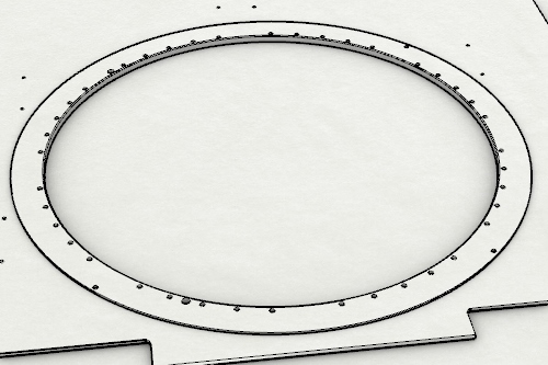
The Tiger's submersion ability was deleted in September 1943 [3, see 3.4.1.5] . The holes at front left for submersion equipment should have been deleted then. Therefore, for the rest of the production run, this was the turret seating ring.
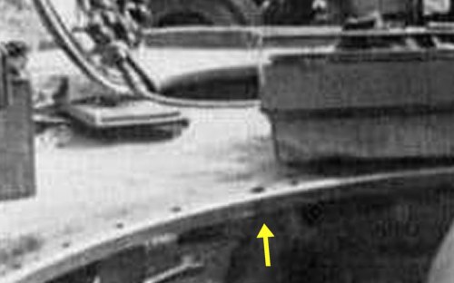
This is from a photo of a "Mid" Tiger hull undergoing maintenance. We can see a portion of the turret seating ring behind the driver's station. I have pointed out the large hole for a locating pin.
[1] Survey of Tiger 250122, at Bovington museum, by David Byrden
[2] Survey of Tiger 250122, at Bovington, by Hilary Louis Doyle
[3] Germany's Tiger Tanks, volume 1 : DW to Tiger 1
[5] Survey of vehicle 251114, at Saumur, by Jean-Charles Breucque