The turret bearing
The Tiger I had a fully rotating turret carried on a ball-bearing race.
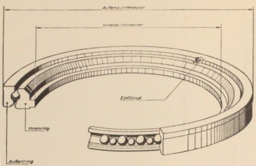
This diagram, extracted from a manual [3, see plate 65] , represents the first version of the device. Ball bearings are trapped in a "race" between two concentric steel rings. The overall diameter ("Außendurchmesser") is 2100mm [3, see page 9] in all versions. The inner diameter is 1836mm in this version.
The original design
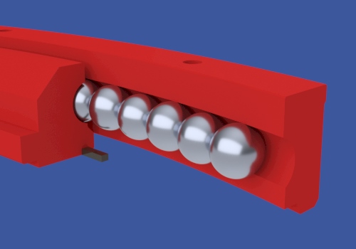
The original design of the device had 158 ball-bearings, their centers lying on a circle of 1990mm diameter. Every second ball was load-bearing [1, see page 89] with diameter 40mm. Between them were "spacer" balls of diameter 39mm. The ball race was "crowded", with very little space between balls, as this model demonstrates.
The steel rings have been sectioned in this model. The inner ring, on the left of the image, has a complex profile because it carries a rubber seal for submersion (not included in this model).
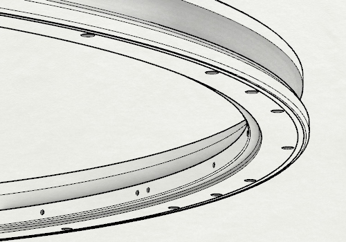
The inner bearing ring has 24 evenly spaced bolt holes on its underside. Beside each one is a hole on the inside face (or a pair of holes) for attaching the main rubber seal. There are an additional 8 holes on the underside for screws that fix a "toothed ring" under the bearing ring.
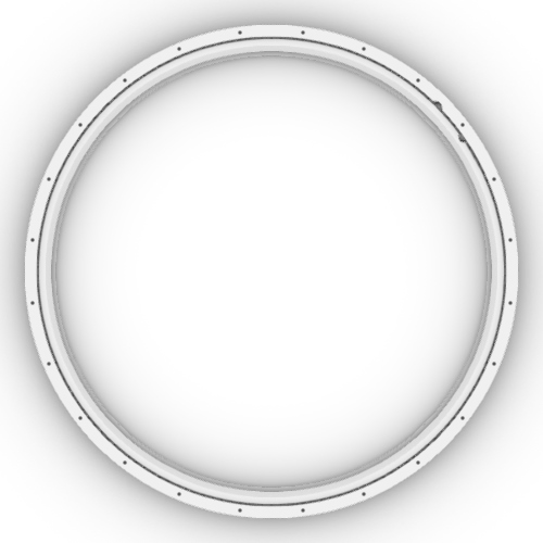
This top view of the complete bearing shows that the outer ring also has 24 bolt positions where the turret's "support ring" can be attached. And we can see two additional details: both rings have a small notch.
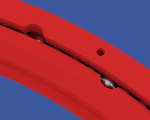
These two "filling notches", when brought together, form a "filling hole" through which ball bearings can be inserted into the space between the rings. I don't know if these notches were supposed to be at specific angles on the ring when the bearing race was installed in the vehicle. But however they might be oriented, it was not possible for them to line up when the turret was locked in the forward position.
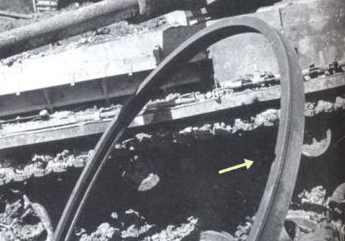
This is an outer bearing ring from an exploded Tiger. I have pointed out its "filling notch".
Additional bolts
The original ball-bearing race was used on the first 200 Tiger turrets (and, presumably without the submersion features, on the Tiger P). Feedback from the troops indicated that the attachments of the tank's cupola and turret were weak points. Starting with the 201st tank, the number of bolts in those joints was increased [2, see 3.4.2.13] .
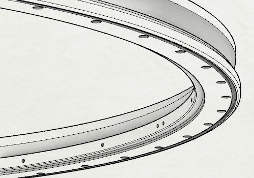
The underside of the inner bearing ring now looked like this. It had 48 evenly spaced bolt holes. Eight of them were still dedicated to screws for the toothed ring, and the other forty linked the turret to the hull.
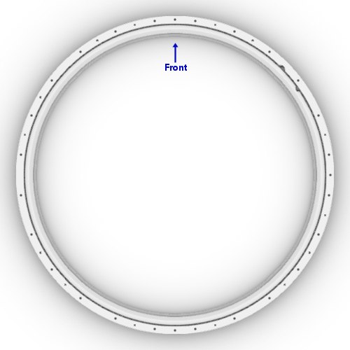
In the outer ring, as this image shows, there were some gaps in the new sequence of bolt holes. Various mechanisms on the turret ring had been positioned between the original 24 bolts, and now made it impossible to use all of the interstitial positions. The upper ring therefore attached to the turret at one specific angle, with its insertion notch at 45 degrees right (1:30 o'clock) as shown here.
This, the second version of the bearing ring, was used in all of the subsequently built "Early" turrets.
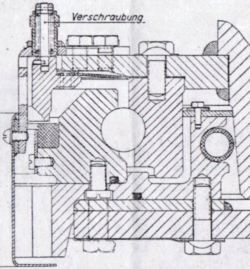
This is a cross-section through the "Early" turret ring and hull roof. The ball-bearing race is in the middle of it all [3, see plate 8] , sitting on the toothed ring. The turret's armour wall is at the extreme right. The horizontal pane at bottom right is the hull's roof plate, which has a seating ring welded on top of it.
When the "new" turret was introduced in July 1943 it had a new ball bearing race.