The Tiger had a torsion bar suspension, with eight equally spaced bars per side. Each torsion bar was anchored in a hull wall at one end, ran all the way across the hull and into a swing arm axle, with most of the swing arm being outside the tank. The two sets of torsion bars could not occupy the same space within the hull, so they were displaced from each other and the difference was compensated by trailing the swing arms on the right side and leading them on the left.
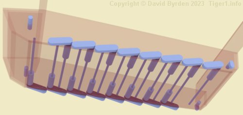
This simplified model of a partial Tiger hull shows the sixteen torsion bars, and the swing arms at their ends. Because their spacing is precisely known, they make a good reference grid for specifying the shape of the hull.
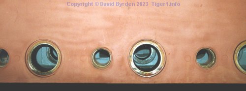
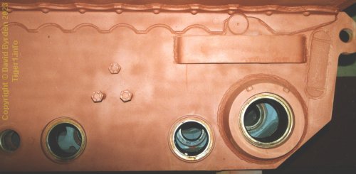
The torsion bars could be removed without entering the vehicle, by pulling them through their anchors. Therefore, as you see in this photo, the hull walls had small holes for withdrawing and inserting torsion bars, interspersed between large holes for the swing arms.
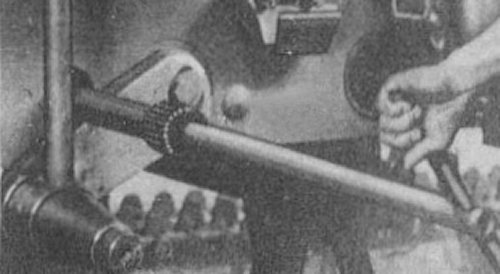
This photo from a manual [4] shows a bar being inserted. Note that the adjacent swing arm must be held down forcibly for access to the small hole.
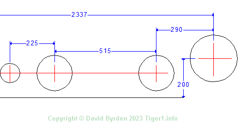
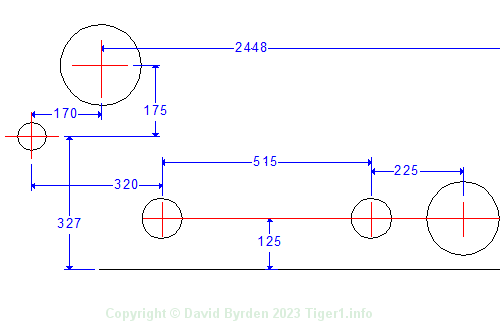
At the rear of the tank, the idler wheel literally pushed the tank along, therefore it had a very solid bearing for its adjustable arm. This diagram shows the spacings of the axles. I am a little uncertain of the distance "290mm" because it derives from my own measurements of a Tiger. All other figures quoted here are from German documents.
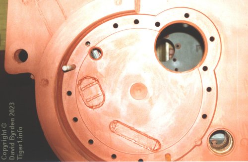
At the front of the tank, drive shafts protruded through the side walls. The axle of the sprocket wheel itself did not penetrate the wall, but a coaxial notch was made as a reference for drilling these bolt holes. The final reduction gearbox was attached here.
[1] Drawing J3154 : "Einbau des ZF. 12 Gang Elektro Getriebe."
[2] Survey of Tiger 250122, at Bovington museum, by David Byrden