Shape of the torsion bars
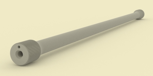
The Tiger 1's suspension consisted of 8 swing arms per side, each with multiple wheels. Every swing arm was sprung by a torsion bar (Drehstabfeder) inside the hull. This is a model of one. A torsion bar is a spring that is straight rather than curled.
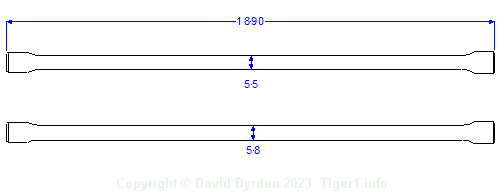
Most of the Tiger's torsion bars had a diameter of 55mm. The first and last bar on each side were stronger than the rest, with a diameter of 58mm [1, see Anlage A] . The overall length was 1890mm. We don't seem to have original diagrams of these bars, but design drawings for the similar torsion bars of the Tiger II have survived [7] [6] , and they contain the bars' performance calculations as well as their shape (caveat: the Tiger II bars are thicker and longer than these ones.)
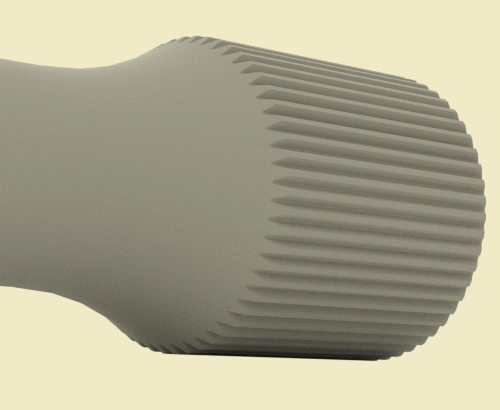
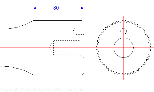
The splined ends of a torsion bar are usually made thicker than the rest, to reduce the stress at the vulnerable roots of the teeth. The Tiger's bars were splined exactly as per the DIN 5481 standard. The fixed end of each bar had diameters of 80mm (minimum) and 85mm (maximum), and 55 teeth. The free end had diameters of 75mm and 80mm, and 51 teeth. [2]
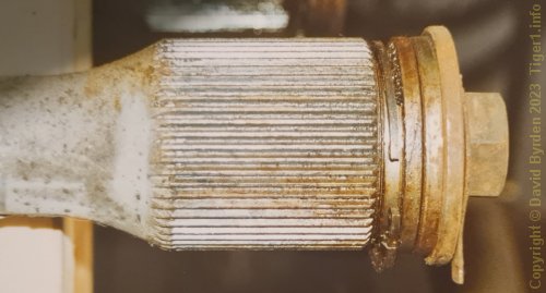
Both ends of the bar were drilled with a threaded hole for attaching end caps. This is the fixed end of a torsion bar from Tiger "131" at the Tank Museum. Two capping discs are attached to it by a large bolt (41mm across faces).
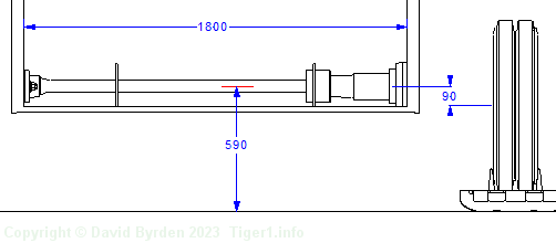
The bars were mounted inside the hull, as close to the floor as practical. This diagram shows the hull at its default height above ground level. The fixed end of the torsion bar is mounted on the wall at our left. The free end is inside the swing arm, which is not completely drawn in this sketch. At the right you can see some of the road wheels, standing on the track.
Design considerations
Torsion bars are often pre-stressed during manufacture, resulting in "left handed" and "right handed" bars that should not be mixed up. But the Tiger's swing arms were leading on one side of the tank and trailing on the other, so this problem could not arise.
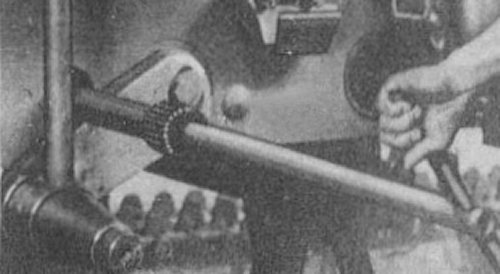
The ends of the bar had different diameters to simplify the insertion and removal of the bar. This photo from a manual [4] shows a bar being inserted through the hull wall. There is a splined anchor sleeve just inside this hole. The thin end of the bar passed through it without touching, but this end, the thick end, will engage with it. Note that the adjacent swing arm is held down by a pole to give access to this hole.
The different numbers of teeth fortuitously allowed the angle of the torsion bar to be adjusted by half-degrees. According to a German manual [5] , "if you turn the small head forwards by one tooth, i.e. by 7.06°, and turn the large head backwards by one tooth, i.e. by 6.545°, that yields a difference of 7.06° minus 6.545° = 0.515° ". It was necessary to carefully adjust the torsion bars so that the road wheels would share the weight equally.
[1] Der Panzerkampfwagen VI und seine abarten, Walter J. Spielberger, Motor Buch Verlag
[2] British drawing of torsion bar, dated 17.5.1944
[3] Survey of Tiger 250122, at Bovington museum, by David Byrden
[4] D 656/21 "Panzerkampfwagen Tiger Ausführung E"
[5] Panzerkampfwagen Tiger Ausführung E ; Driver's Handbook ; D 656/23