The reduction gearboxes
The Tiger's drive train included a final reduction gearing that brought the high revs of the engine down to the ponderous wheeling of the sprocket, while of course scaling up the torque. This gearing was located in two sealed housings placed outside the hull, partially protected by the sprocket wheels themselves. The gearboxes were identical and, with a little reconfiguration, could be used on either side of the tank.
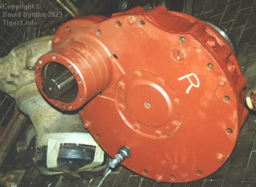
This is one of the reduction gearboxes. We are looking at the side that abuts the tank's side wall. It does not actually touch the wall, because several large bolt heads around its rim hold it clear of the wall. It is attached to the tank by long bolts around its edge. The tube at our left contains the drive shaft, and the silver attachment near the bottom of the photo is where lubricating oil enters the gearbox.
The photo was taken during restoration of Tiger "131". The restorers have marked this gearbox with an "R". The unrestored left-side gearbox is behind it.
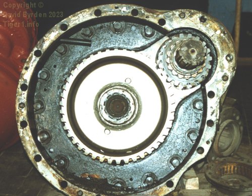
With the flat side removed, we can see into the gearbox. The drive shaft is at upper right. The gearbox has an internal partition and there are additional gear wheels hidden behind it.
Positions of the gearboxes
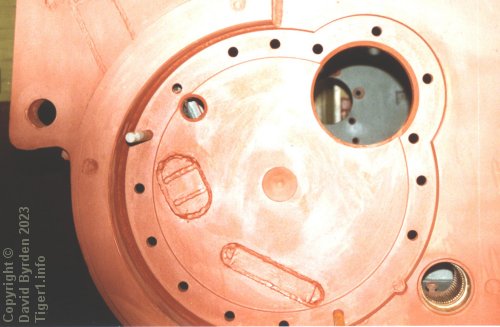
Their attachment to the hull side wall was via either 16 (left side) or 17 (right side) bolts. This is the left side of Tiger "131" during restoration. A shallow recess is machined into the wall and the bolt positions run all around it. Note that two of the bolts are permanently fixed in the wall because the armour plates on the other side make them impossible to remove.
At bottom right of the photo you can see that one of the bolts for a torsion bar lies within the recess, and a notch is made for it. This is a special short bolt. One fixing bolt is omitted from the reduction housing here, to make room for the torsion bar.
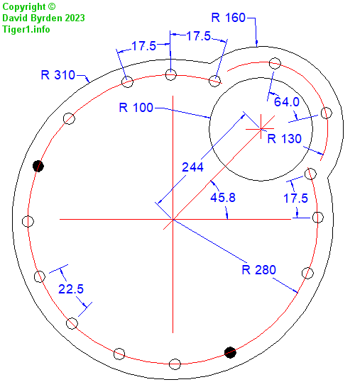
These are the basic dimensions of the bolt holes and recess in the left-hand wall. Most of the bolts on the large circle are regularly spaced, but a few of them are shifted by 5 degrees. Note that the reduction housing itself is tilted at 45.8 degrees, not 45, which affects all of the bolt positions.
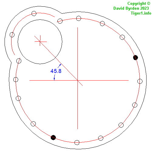
This is the recess in the right-hand wall. The permanent bolts are drawn as filled circles. Again, the gearbox is not at exactly 45 degrees.
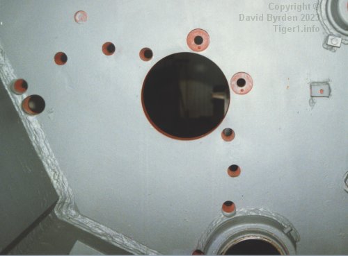
This is the right-hand wall seen from inside the bare hull.
The bolt plate
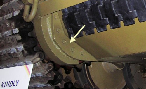
Some of the long bolts that attach the reduction gearbox, terminate outside the hull. They are nutted to a flat plate, indicated here. It provides protective recesses for the nuts which would be inconvenient to drill into the side armour plate. The plate is not fixed to the hull.
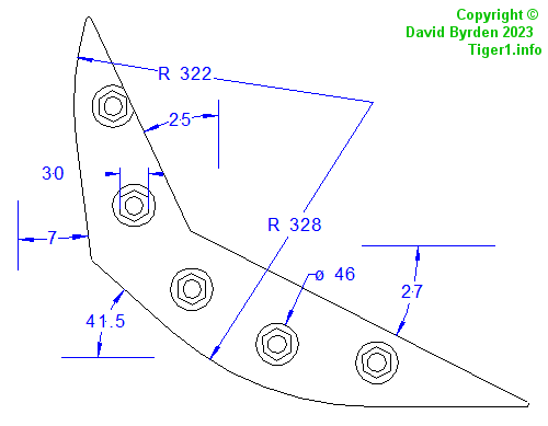
There was a few millimeters variation in the manufacture of these plates; this is a typical example. The nut positions are given in the other diagrams. The upper edges of the plate conform in angle to the main armour plates of the lower hull.
[1] Survey of Tiger 250122, at Bovington museum, by David Byrden
[2] Der Panzerkampfwagen VI und seine abarten, Walter J. Spielberger, Motor Buch Verlag