The Maybach HL210, the Tiger's original engine, was designed for operation in dusty "tropical" environments as well as European ones. Although the engine had three conventional oil-bath filters for its combustion air, it allowed additional filters to be attached if required.
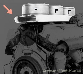
This is the forward end of a HL210. Its air filters are each marked "F". They sit on an air duct with an open end, marked with an arrow.
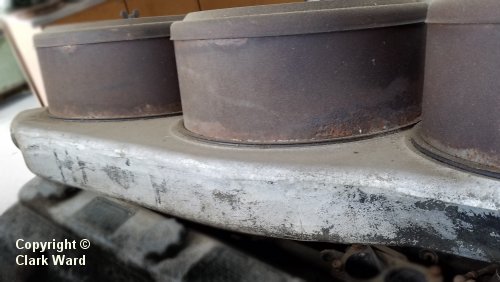
The duct is a hollow metal casting. This example in a museum has been detached from the engine.
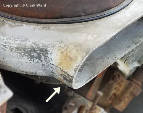
The opening at the front of the duct is a parallel-sided tube to which you can connect additional items via a simple sleeve joint. The tube is flattened to save height.
At Henschel, the Tiger's designers created the "Feifel" air precleaner system for their tank. At first they planned to link the precleaners directly to the connector on the Maybach engine. The engine's duct would then have been an integral part of the "Feifel" system.
But they changed their minds, and allowed the engine to draw air from the sealed engine compartment. Therefore, the duct served no purpose. The next generation of Tiger engine, the HL230, had no air inlet duct.
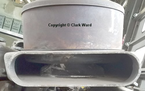
The filter canisters had both their inlets and their outlets on the underside. The duct therefore had to bring the incoming air to them, while keeping it separate from the filtered air. Peering into the duct's opening, we can see how this was done. There is a second duct nested within, supporting the filter canisters, collecting their output air and leading it to the bottom of the outer duct. This internal duct is the only one doing any useful work.
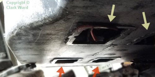
There are four openings on the bottom of the outer duct where the filtered air emerges. The engine's four carburettors connect directly to them.
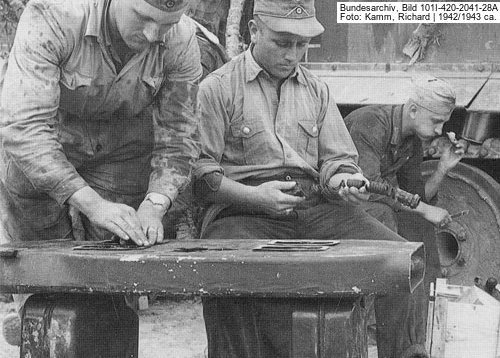
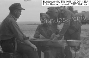
This is a HL210 duct, from Tiger "02" being maintained in Tunisia. The mechanic has turned it upside down and is checking the seals on the outlets.
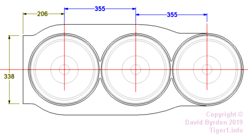
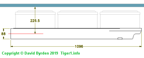
These are the basic dimensions of the HL210 air duct. The second diagram also shows the relation of the duct and filters to the engine hatch above them. (Green numbers are quotes from German design drawings; blue numbers are obtained by measurement.)
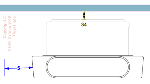
The sides of the duct were tapered, because it sat between the cylinder heads. The free area of the duct's intake was 243 square centimeters.
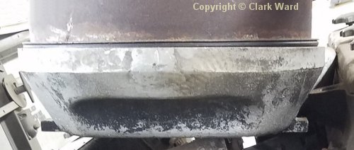
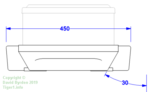
The rearmost third of the duct was narrower, more tapered, and had an indent to avoid colliding with a water pipe on the engine.
[1] Survey of vehicle 251114, at Saumur, by Jean-Charles Breucque
[2] Workshop drawing 021 B 425 B1 : HL 230 external dimensions