The Tiger's hull was reinforced by a number of struts welded firmly to the hull floor and walls.
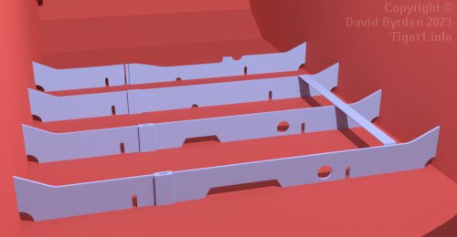
Four transverse struts ran across the front of the hull. They had various holes cut into them for drainage and for items of equipment. The foremost strut had a wide notch allowing clearance for the main gearbox.
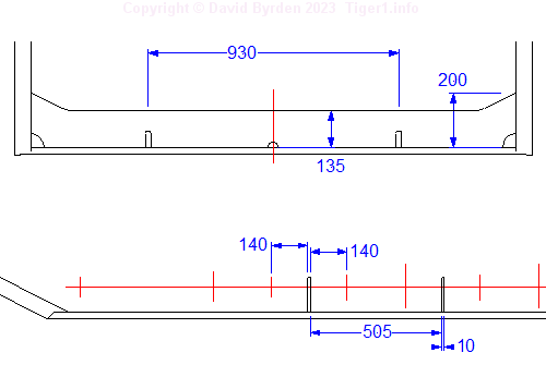
These are the basic dimensions of the transverse struts. They were placed at intervals of 515mm, the distance at which the suspension system repeats, because they had to fit between the torsion bars.
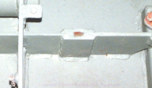
To allow for variations in the size of Tiger hulls, these transverse struts were each made of two pieces, firmly welded together using small steel rectangles. This photo shows one of the joints.
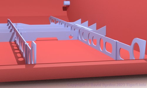
Two primary longitudinal struts ran all the way along the bottom plate, meeting the front and rear walls. They are visible in this model. We are facing toward the front of the hull.
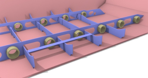
These struts had a series of holes in them; round holes for the inner bearing rings of the swing arms, which are installed in this model; and wide holes that torsion bars would pass through without contact.
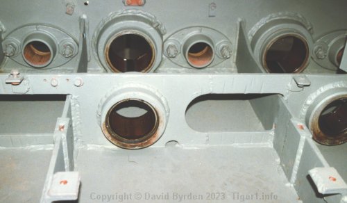
Some of the wide holes were shaped to interlock with the transverse struts. This photo shows the swing arm bearings and the interlocks between the two kinds of struts.
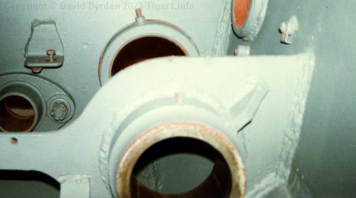
Large, reinforced bearing rings for the idler wheel arms were carried at the rear ends of these struts.
[1] Survey of Tiger 250122, at Bovington museum, by David Byrden
[2] Drawing J3154 : "Einbau des ZF. 12 Gang Elektro Getriebe."
[3] Survey of vehicle 251114, at Saumur, by Jean-Charles Breucque