A number of mechanical and electrical features adorned the walls of the Tiger's engine room. Here I will briefly enumerate the items mounted upon the upper walls, ignoring the engine and items on or near the floor.
Electronics hub
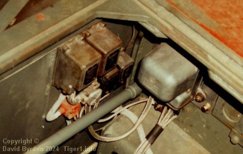
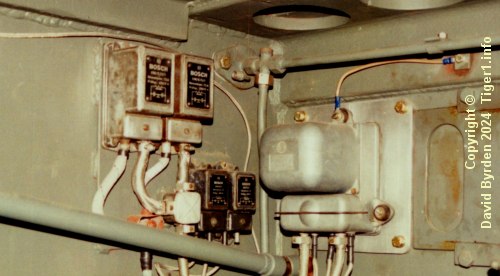
In the forward left-hand corner, the tank's central electronic hub comprised a number of metal-cased devices. This photo shows the Tank Museum's "131" during restoration [7] . Almost all of these appear to be the original parts, except for the voltage regulator, which I discuss separately.
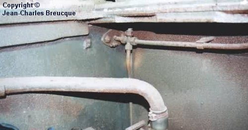
In February 1944, after about 40 Late Tigers had been manufactured, all of these electronics were moved into the crew room [8, see 3.4.1.22] , leaving only the fuel lines in this corner. [9]
Voltage regulator
The HL210 engine required a 1kW voltage regulator, and its replacement the HL230 required only a 700W regulator. The German diagram that explains how to upgrade from the older engine to the newer one, also specifies that the voltage regulator must be replaced [1] .
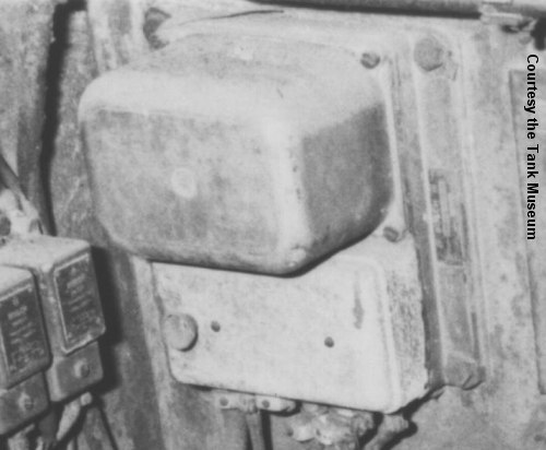
This is the 1kW regulator found in the Tank Museum's Tiger "131" upon capture. Another regulator of this type is installed in Tiger "712", and is photographed in detail in a book [11, see photos 310-314] .
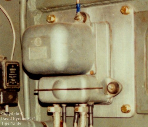
The restoration of Tiger "131" included an engine upgrade to the HL230, and the restorers duly swapped out the tank's voltage regulator for an original German 700W regulator. In this 1990s photo of Tiger "131", we see that this regulator has three rather than four fixing bolts, and its fuse box (the lower box) is much smaller.
But the square base plate in this photo is not a German part. This regulator, like the other one, was supposed to bolt directly to the firewall. [1]
Tail lamp cable
A thin electrical cable ran along the top of the left-hand wall. It was the power cable for the tank's tail lamp.
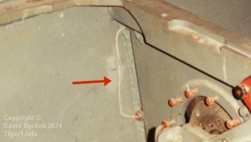
It descended in the rear left-hand corner to pass through the wall via a watertight port, arriving into the side compartment below the main fans. [7] [6]
Control rod fulcrums
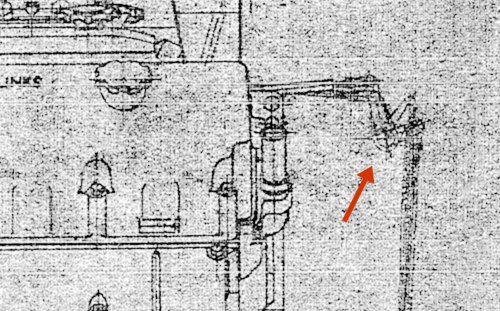
Among the engine controls were two rods. They rose from the crew compartment into the engine compartment, and each was connected by a fulcrum (arrowed) to rods on the engine. [5]
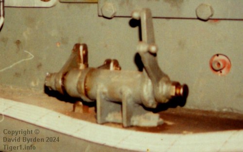
Both of the fulcrums were built into this device on the back of the firewall. [7] In this photo the engine and its horizontal rods are missing, but the vertical rods from the crew room are connected.
Battery switches
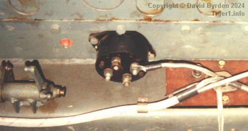
The main power switch for the tank's entire electrical system was originally on the back of the firewall, as seen here. In February 1944 it was moved into the crew room along with the other electrical equipment from the engine room.
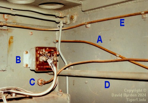
The item at [B] is the battery changeover, switching the batteries from parallel to serial when the engine is started. This example in Tiger "131" is lacking its cover plate. This device was also moved to the crew room in February 1944.
Air conduit
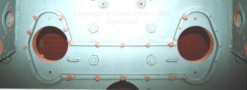
A flat air conduit was attached to the rear wall. Here is the conduit wall with its covers removed. Its internal space was only 30mm thick.
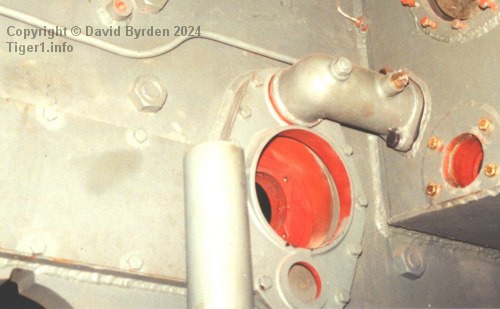
The conduit collected hot air from the exhaust pipe sleeves, which connected to the large hole here, and sent it to the main output fans via the small tube. The small hole in the conduit is for maintenance.
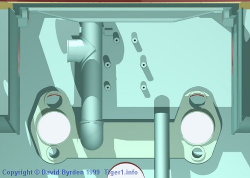
At first, there was a large vertical pipe leading from the conduit to a port on the engine decking, which vented into the engine room. The pipe is represented in this model. It was used during submersion, and was deleted when the submersion capability was discontinued, halfway through "Mid Tiger" production.
Fan drive gearboxes
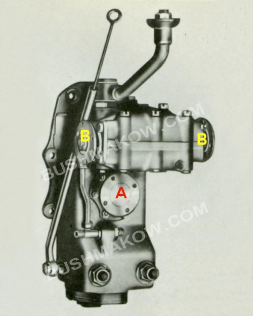
The first 250 Tigers had the HL210 engine and also this fan drive gearbox on the inside rear wall of the engine room. It allows the HL210, connected at [A], to power both fans via shafts that connect at [B]. [10, see Tafel 44]
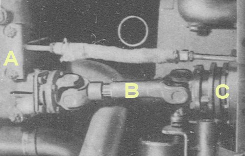
This view from above shows the gearbox [A], one of its fan drive shafts [B] and a mechanical clutch on a side wall [C]. [2, see Abb.17] This equipment was all deleted when the HL230 engine was introduced, at the 251st Tiger in May 1943.
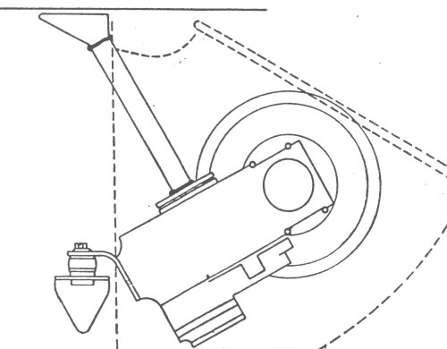
The replacement engine, the HL230, required two new gearboxes to drive a Tiger's fans. This sketch shows the one on the right-hand engine room wall. The dotted outline represents the fan duct on the other side of the wall.
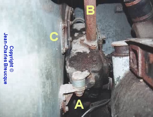
This is the right-hand fan gearbox installed in the Saumur Tiger before restoration. Its support, with rubber shock absorber, is at [A]. The oil filling tube is at [B]. [9]
Drain control
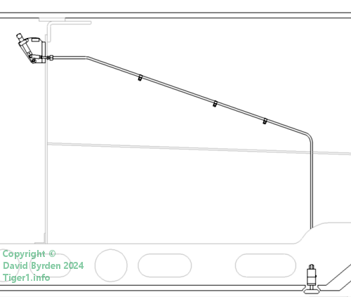

Starting with the 50th Tiger [10] , a cable for the floor drain ran along the right-hand wall, seen here at [A]. [7]
Clutch control
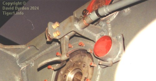
The fan clutches in HL210-equipped Tigers had to be disengaged before submersing the tank. This could be done without opening the engine hatch. This photo shows the place where the left-hand clutch would be installed. The U-shaped gripper (when rotated vertical) would slot into a groove on the clutch housing, pushed by the two yellow springs above it. By twisting the shaft at top right of this photo, you could engage and disengage this clutch.
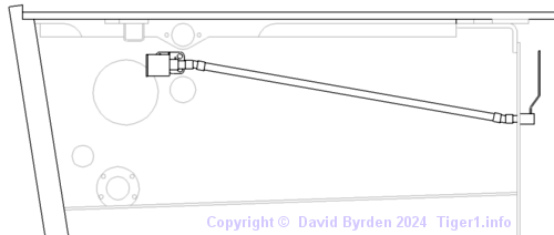
The shaft was rotated by a large handle on the front of the firewall. This is a view on the left-hand engine room wall, showing the shaft. By running this shaft directly to the axle of the gripper device, they kept it away from the wall, leaving space for a vertical pipe (the pipe was used to share hot water between Tigers [3] ).
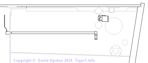
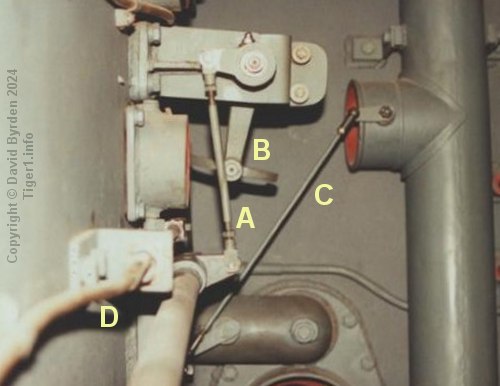
On the right side of the Tiger there was no oil filler pipe, so the right-hand control shaft was placed very close to the wall. Since it could not terminate on the axle of the gripper mechanism [B], it was kept horizontal and was connected to the gripper by an additional rod [A].
These clutch control mechanisms were installed only in the first 250 Tigers, and were removed if the tank got upgraded to the HL230 engine.
Side valve controls
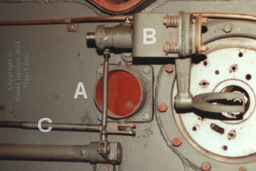
Each side wall of the engine room had an air outlet [A] leading directly into a main fan duct. It had a valve, which is closed in this photo. At first, this valve was linked to the clutch control mechanism [B] by yet another rod. But later, anticipating the arrival of the HL230 engine and the deletion of the clutch controls, the designers added a separate push-pull cable [C] for each valve.

Each one was controlled by twisting a knob on the firewall. The right-hand cable is at [C] in this photo. As for the date of this change, a surviving German diagram explains how to upgrade a Tiger's engine, including the addition of these cables; it was signed off on 29 March 1943 [1] . The surviving Tiger "131" had just been built at that time, and it had these new cables.
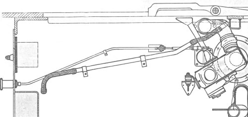
The HL230 engine required two water pipes that were not present on the HL210. In the Tiger, these pipes were attached to the side walls of the engine room. To make room for them, the valve control cables were moved up so that they were above the valve rather than below it (the valve pipe itself was simply flipped).
This diagram was extracted from a German drawing and it shows a valve control cable in the new, higher position, above the water pipe. [1] Since a HL230 engine is present, the old clutch control mechanism is absent and the new type of fan gearbox is on the side wall, as discussed elsewhere. The arrangement of the corresponding items on the left-hand wall mirrored this.

These valve control cables were present until the Tiger's submersion capability was deleted. Thereafter, the hole leading to the fans [C] was built without a valve.
Rear valve controls
At the rear of the Tiger's engine compartment were three valves that were used in sealing the tank for submersion; they linked the exhaust cooling duct to the main fans and to the engine compartment. All three of them were controlled by a single handle on the firewall, linked by a push-pull cable to a sequence of levers and connecting rods.
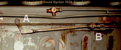
This photo shows the back of the firewall. The lever, when turned by the crew, turns the arm at [A], moving a rod that is connected to the push-pull cable at [B].

This cable [E] runs around the top of the walls to the back of the engine room.
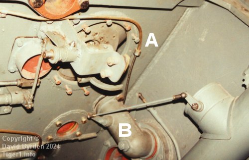
The cable arrives at [A] and is connected to a lever that closes a valve inside the pipe [B]. On that same axle is a connection to the large vertical pipe's outlet, which opens when the other valve closes.
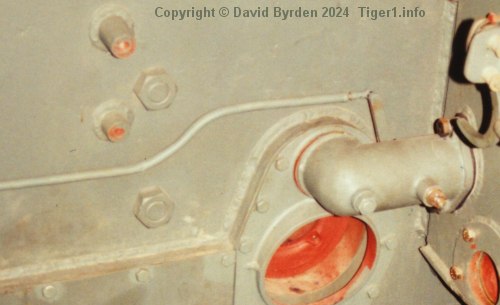
This also moves a push-pull cable in a shaped sleeve that runs along the back wall, ensuring that both outlet pipes close at the same time.
This equipment was deleted when the submersion capability was cancelled during the "Mid Tiger" period. The outlet pipes (as in this photo) were retained but they no longer contained valves.
Water pipes
The Tiger's engine was water-cooled, and a number of thick pipes at the rear of the engine compartment connected the engine to the radiators. I will not discuss them here. But, with the arrival of the HL230 engine in May 1943, two more secondary pipes were attached to the side walls of the engine room.

This is a view of the right-hand wall. The new water pipe is the thicker of the two items on the wall. It has flexible sections at both ends, which lead away from the wall to their connections; the forward end connecting to the engine, and the rear end to the thin bypass pipe that runs above the engine.

Taken from a maintenance manual, this is a photo of the left-hand wall, which mirrors the layout. The new water pipe [A] passes outside the hot-water-sharing pipe [B]. The cable [C] is the side valve control. [4]
Much later, a change was made to these pipes. The German diagram concerning engine upgrades [1] was modified on 6 March 1944 for this reason. It now specified new, thicker pipes. The old pipes (and all submersion equipment) were striken off the diagram.
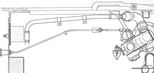
From that diagram I extracted this sketch showing how and where the new, thicker pipes attach to the walls. I have included the valve control cable in the diagram for reference, but it was no longer being installed in new Tigers, and it was now supposed to be removed during engine upgrades [1] .
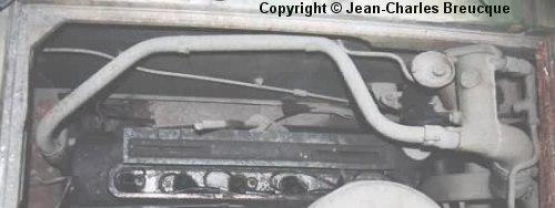
The preserved Saumur Museum Tiger is a good example of the final configuration of the walls. In this pre-restoration photo, the right-hand wall of the engine room bears only the later type of water pipe, and the drain control cable.
[1] German sketch SK3426: engine upgrade
[2] D 656/21 "Panzerkampfwagen Tiger Ausführung E"
[3] Panzerkampfwagen Tiger Ausführung E ; Driver's Handbook ; D 656/23
[4] Pz Kpfw Tiger Ausf.E ; Instandsetzungsanleitung für Panzerwarte ; D 656/30 b und c
[5] Workshop drawing 021 B 425 B1 : HL 230 external dimensions
[6] Survey of Sturmtiger at Panzermuseum Munster, by Rob Veenendaal
[7] Survey of Tiger 250122, at Bovington museum, by David Byrden
[8] Germany's Tiger Tanks, volume 1 : DW to Tiger 1
[9] Survey of vehicle 251114, at Saumur, by Jean-Charles Breucque
[10] Kraftfahrgerät teil 3, Fahrgestell und Turm Panzerkampfwagen "Tiger", heft 60
[11] A MODERN STUDY OF Fgst. Nr. 250031, by Lloyd, Balkwill and Johnson