Drains in the floor
Every Tiger 1 had at least two drain valves in the hull floor, to dispose of rainwater, spilt fuel etc. One of them was in the rear of the engine compartment. It is visible in a photo of the underside of chassis #250002. [1, see page 89]
The Tigerfibel [4] states that the rear drain should be left open when travelling on dry land.
The first drain mechanism
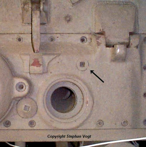
The rear drain was inaccessible due to the engine which almost filled the compartment. Two different mechanisms were invented for controlling it remotely. In the first 50 Tigers [8, see page 7] , it was operated by rotating this lock on the rear decking.

The lock on the decking was connected to the drain on the floor by this shaft with a universal joint [8, see Tafel 2] .
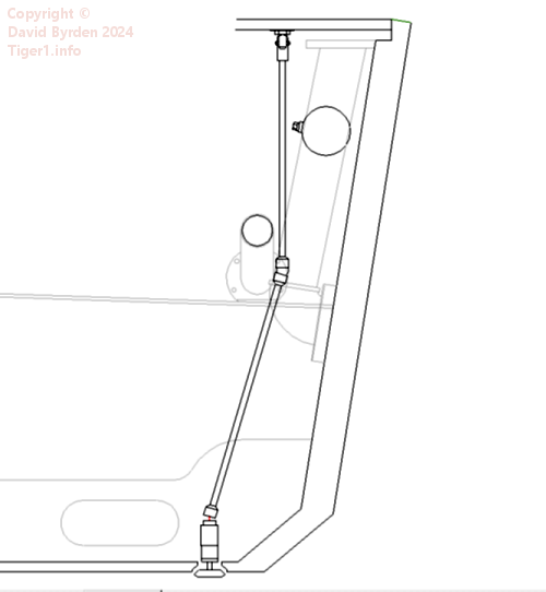
This profile diagram shows how the shaft passed between pipes in the engine compartment. The front of the Tiger is to our left. [2, see photos 231, 233, 236, 246, 262, 271]
The second mechanism
Starting with the 51st Tiger, the lock and shaft were deleted. They were replaced by a lever on the firewall, linked to the drain via a push-pull cable.
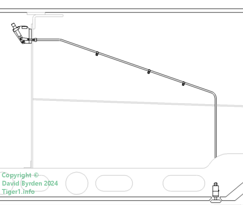
This diagram shows the right-hand engine compartment wall. The new cable is clipped to the wall. The firewall is to our left and the lever is on the crew's side of it. The cable's sleeve diameter is 10mm, and the travel is about 15mm.
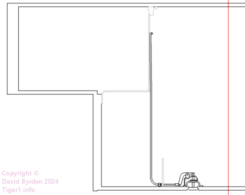
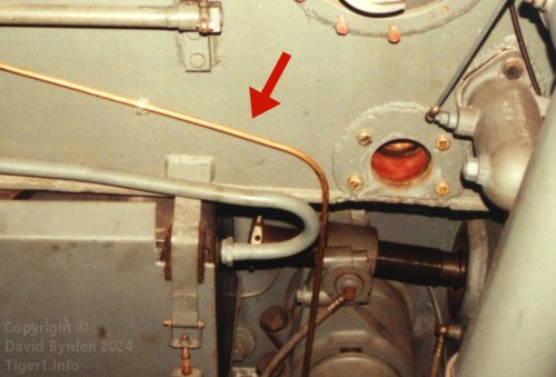
This rear-facing diagram and the photo demonstrate that the push-pull cable must leave the sponson wall and drop down through space to reach the floor. Then it passes through a floor strut to reach the drain mechanism. (This is Tiger "131" during restoration.)
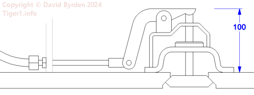
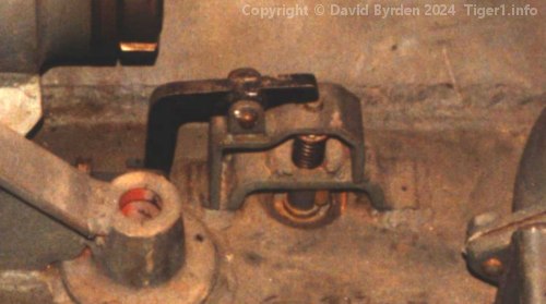
This is the rear drain mechanism. The original bracket carrying the drain plug is welded to the floor, and is identical to the other drain at the front of the tank. A second bracket with a hinged lever has been added on top of it for operation by the cable. It contains a spring to hold the drain shut. [3]
The drain lever
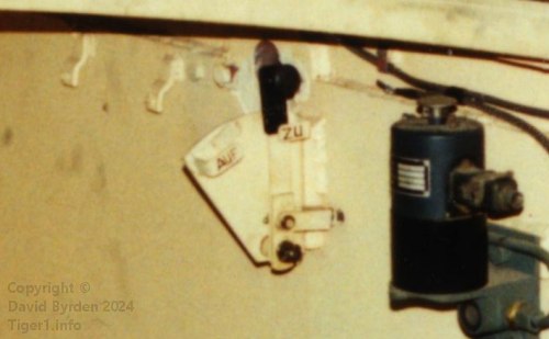
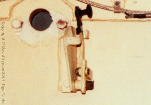
The control lever was mounted on a bracket, bolted to a block on the firewall. This is the lever in Tiger "131" during restoration at the Tank Museum [3]
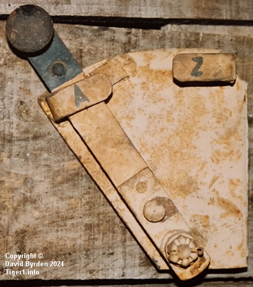
This is the lever in its original paint. It was marked with the letters "A" and "Z"; the restorers have painted "AUF" and "ZU" instead [6] .
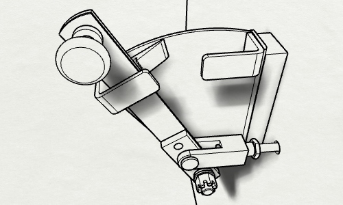
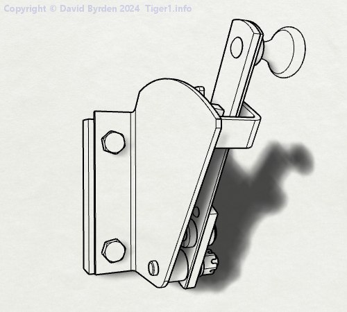
The position marked "Auf" opens the drain, and "Zu" closes it.
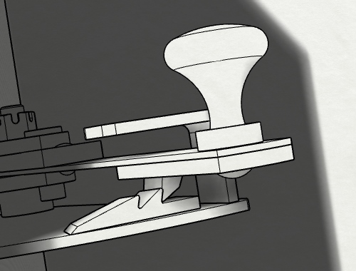
A catch holds the lever at one of two places in the "Auf" position. When the lever is pulled out of this catch, the spring on the drain moves it back to "Zu".
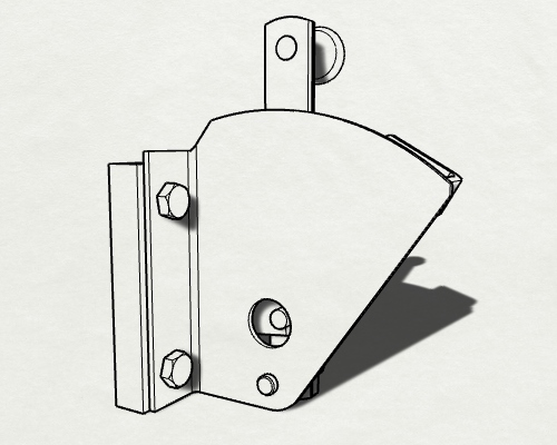
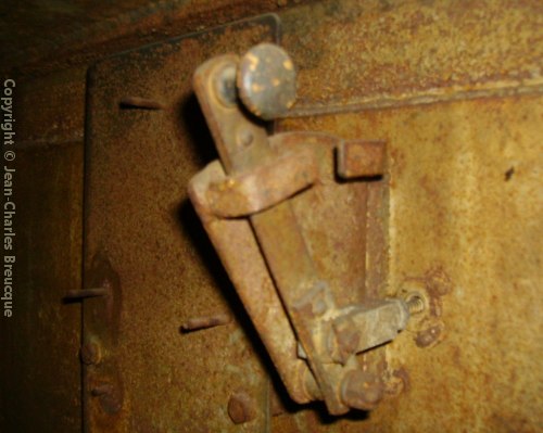
A thousand Tigers later, the control lever was almost unchanged. It had been moved a couple of centimeters because of the introduction of a large circuit board beside it. Also, a hole was now made in the body to simplify maintenance [7] . I don't know when that change happened. The photo shows the "Late" Tiger of Saumur museum before restoration. [5]
Simplified drain
In May 1944, starting from hull #251165, the rear drain bracket was redesigned to have fewer parts [1, see 3.4.1.13 and page 160] .
Sturmtiger
It's not clear if this mechanism was preserved during the conversion from Tiger to Sturmtiger. The surviving example in Munster museum has the remains of the standard drain bracket, but the lever's mounting block has been completely unwelded from the firewall. However, that may have happened when Allied testers added new air filters overlapping its position.
[1] Germany's Tiger Tanks, volume 1 : DW to Tiger 1
[2] A MODERN STUDY OF Fgst. Nr. 250031, by Lloyd, Balkwill and Johnson
[3] Survey of Tiger 250122, at Bovington museum, by David Byrden
[4] Tigerfibel (user's guide for the Tiger 1)
[5] Survey of vehicle 251114, at Saumur, by Jean-Charles Breucque
[6] "Stellhebel für Bodenventil" drawing 021D2702U148
[7] Photographic study of the Saumur Tiger by "Panzerbasics"
[8] Kraftfahrgerät teil 3, Fahrgestell und Turm Panzerkampfwagen "Tiger", heft 60