The Tiger had two large drum brakes, located on the inside surfaces of the side walls, at the nose.
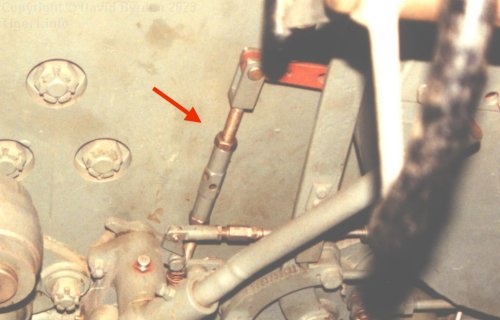
This photo shows the left side wall of the tank; the steering wheel is at the right of the photo. Behind it you can see part of a brake housing.
The indicated control rod is the actuator lever for that brake drum. It is pulled by a cam in the mechanism at the bottom of the photo, and ultimately by the brake lever that slants across the photo. That raises the question of how the corresponding brake at the other side of the tank can be controlled from the driver's station.
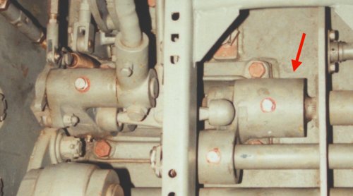
Looking down at the mechanism from above, through the driver's seat support, we can see the brake lever again. Its connection to the cam is not obvious.
The cylinder that I point at is a fixed bearing, containing one end of a shaft that runs all the way across the hull, under the gearbox. It is via this shaft that the other brake is controlled.
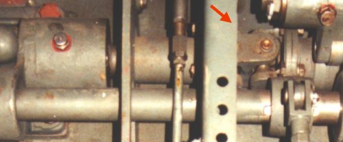
Again, the connection of the right-hand brake lever to the actuator shaft is not easily visible. But we can see something interesting here; the shaft has a universal joint.
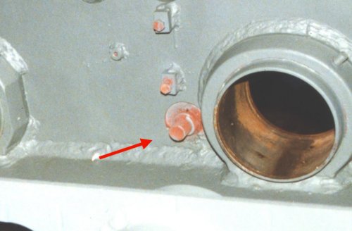
Over at the other side of the hull, there is no complex mechanism. This hull has been stripped bare and we can see that the shaft terminates in a simple post on the wall.
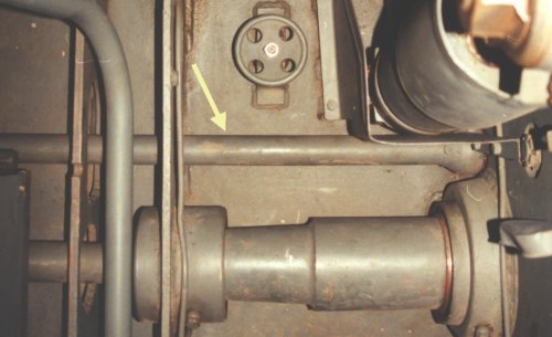
Looking at the same place with all of the equipment installed, we can see the actuator shaft (arrowed). It has a cam at its end that connects to another brake control rod just like the first. Unfortunately that is all hidden behind the shock absorber at top right of the photo.
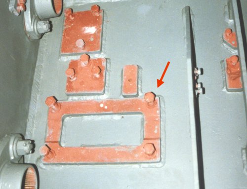
The mechanism that combines the shaft bearing, the left-hand cam, the left-hand brake lever and other items, attaches to the hull floor at this mounting plate.
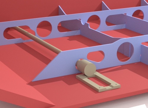
This model shows how the mounting plate sits among the floor struts. There is a hole in the nearby strut for the actuator shaft to pass through.
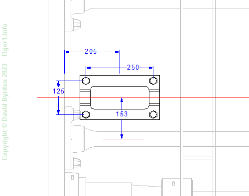
We are fortunate in that German drawings of these items still exist.
[1] Survey of Tiger 250122, at Bovington museum, by David Byrden