About this detail of the Tiger
The engine of the Tiger E was water-cooled. Water was propelled through it by a small pump located at the top front of the crankcase. There is a full description of the pump, with diagrams and photographs, in [2, see pp. 179-180] . There are photographs of assembled engines, with this pump clearly visible, in [4] .

This HL 230 engine in Saumur museum is missing its air filters. The museum staff have painted it to indicate its functional areas. The water pump, indicated here, is painted blue.
The pump consisted of an iron casting containing an impeller. A long shaft running beneath the engine's air filters allowed the flywheel to drive the impeller.
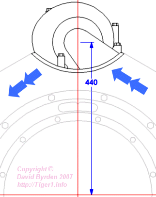
This diagam [1] shows the front of the engine. The pump is bolted to the top front of the crankcase. Water enters (at your lower right) from a coring within the crankcase wall. The impeller pushes it into a curved duct that forms the outside of the pump housing. It passes from the pump into another coring in the crankcase, leading back to the cylinders.
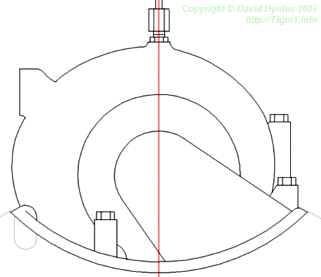
The HL 230 engine was an improved version of the HL 210. Its pump housing was modified by the addition of a square lug on the right side (at your left in this diagram). This lug was used to attach other equipment (at first the fan clutch control rod, later the cold-weather starter). Also, a bolt was moved.
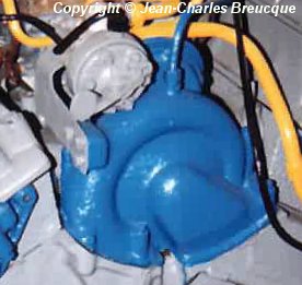
The Saumur engine has this lug. The grey device attached to it is the cold-weather starter.
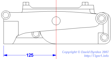
This view from above shows the new lug (at the bottom left of the diagram). You can see that the output duct grows wider so that it can gather more water as it passes the impeller.
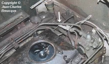
This photograph [3] shows the front of the engine in the Tiger at Saumur museum. The pump is unfortunately hidden below the cold-weather starter device. We can see the three bolts that attach this device to the lug (arrowed, at bottom right).
A narrow pipe was attached to the top of the output duct (arrowed, center). German diagrams label it as the "water pump overflow". In HL 210 engines this pipe was attached to the upper back of the pump; in HL 230 engines, as seen here, it was at the top.

The overflow pipe is arrowed in this diagram. It leads to the rear left of the engine.
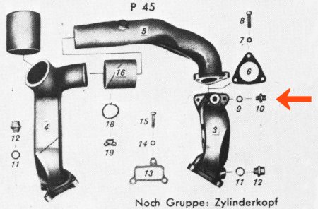
This German diagram shows the outlet pipes for cooling water on a HL 230 P45. The overflow pipe terminates in the junction indicated.
[1] Workshop drawing 021 B 425 B1 : HL 230 external dimensions
[3] Survey of vehicle 251114, at Saumur, by Jean-Charles Breucque
[4] Der Panzerkampfwagen Panther und seine abarten, Walter J. Spielberger, Motor Buch Verlag