About this detail of the Tiger

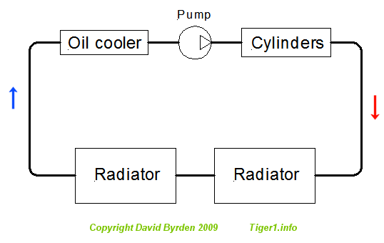
The HL210 engine designed for the Tiger was water-cooled. As this schematic shows, cold water entered the engine at the oil cooler. After collecting heat from the oil, it was led to a pump and thence to the cylinder heads to collect more heat. Finally it went to the radiators to shed that heat.

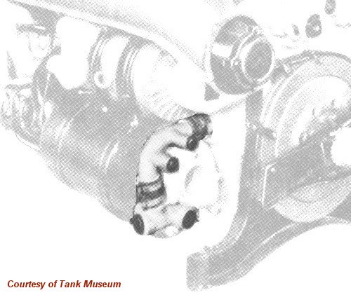
It seems that the HL210 engine had a bypass pipe so that water could circulate within the engine. I don't know the function of this pipe. It is visible here, in this British photograph of an early HL210. It seems to lead water from the cylinder outlets into the oil cooler. It wraps around the main inlet of the oil cooler. The bypass pipe seems to have controls on it; I would assume there is a valve to close it.

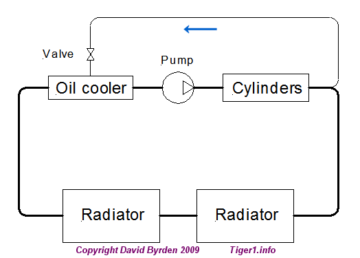
Assuming that the bypass pipe had a valve, the cooling-water schematic looked like this.

This German diagram shows a later HL210 designed for a Panther tank. The bypass pipe is indicated. In this engine, the oil cooler is slightly different, and located further forwards. The pipe is now redesigned with a slant.
In May 1943 the HL 210 was replaced by the HL230, which apparently had the same bypass pipe.
Later on, an engine warmup system was designed for the large German tanks. It worked by heating the engine's cooling water. To allow the connection of this system, the bypass pipe was modified.

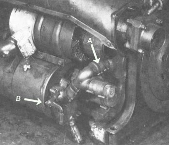
This photo of a HL230 shows the modifications. The bypass pipe (A) has an inlet added for the hot water from the new system. A spring-loaded handle is added at (B) so that the valve in the bypass pipe can be operated remotely.