About this detail of the Tiger
The gap between the Tiger's turret and hull top was nominally 10mm. In early 1943 there were complaints from the troops that shrapnel could lodge in this gap and jam the turret [3] . To prevent this it was proposed that an armour ring be fixed to the hull top, surrounding the turret and protecting this gap.

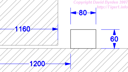
A preliminary design was drawn up for a ring 80mm wide and 60mm deep, having an internal radius of 1200mm. The diagram above shows how this ring would have protected the bottom edge of the turret. This diagram is based on a German original dated 23 March 1943.
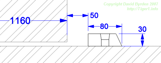
But this initial design was not implemented. About a year later, the designers completed a better design for the ring and it appeared on production Tigers from hull #850 [3] . Drawings have survived, dated 1 May 1944 [4] . The German name for this ring is Turmfugenschutz.

The diagram above is a profile of the actual ring used on Tigers. By now the turret was redesigned with a front radius 10mm larger than before, so the radius of this ring was increased by 10mm. The ring's height was now only 30mm. To help deflect projectiles, its outer face was slanted. The turret was very close to the engine hatches behind it, so this ring could not extend all the way around. Its rearmost corners were about 20mm from the engine vent covers.
The ring was made of three identical segments, spanning 95 degrees each. The ring segments were bolted to the hull top. The bolts had flat tops and were countersunk into the ring. The nuts were on the underside of the hull roof. You can see these nuts in the Saumur vehicle on this site.
The three segments of the ring were identical, interchangeable parts. An original German drawing of the ring survives [3] . It lists the components of the ring as 3 segments with the same part number, plus 15 nuts and bolts. But the designers were unable to use identical bolt positions in all three segments. There were too many items already fixed to the underside of the hull roof.

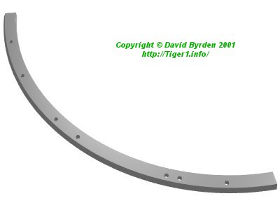
Therefore, the designers put enough holes in the segment to accomodate all the different bolt positions for the front, left and right parts of the ring. The segment had 7 holes but only 5 were used. Different parts of the ring used different selections of the holes. The above is a CAD model of a segment.

This is a segment dug up in Belarus in 2003 (thanks to Nikolai Panov). It is upside down, and a short length is broken off the end.

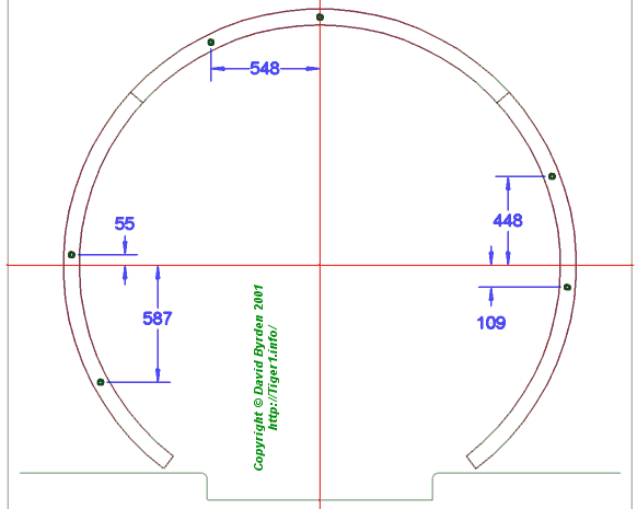
This is my diagram of a ring segment. Green dimensions are quoted from German drawings. Blue ones are obtained by surveying vehicles and may be a few millimeters wrong.
The diagram above shows the bolt positions, the unused bolt holes, and the obstacles that caused the trouble: the supporting bolts for the ammunition racks, and the roof braces.
This CAD model shows the top hull plate of a late Tiger. The bolts in the ring are almost invisible because the bolt heads are level with the top of the ring. There are 6 unused bolt holes, of 22mm diameter, 2 holes per segment. Notice that they are very deep, and unevenly spaced.

This is another diagram showing where the unused holes appeared.
[1] Survey of vehicle 251114, at Saumur, by Jean-Charles Breucque
[2] Survey of Tiger 251113 at Vimoutiers, by Jean-Charles Breucque
[3] DW to Tiger 1

