The Tiger I had a fully rotating 11-ton turret. It was carried on a ball-bearing race.
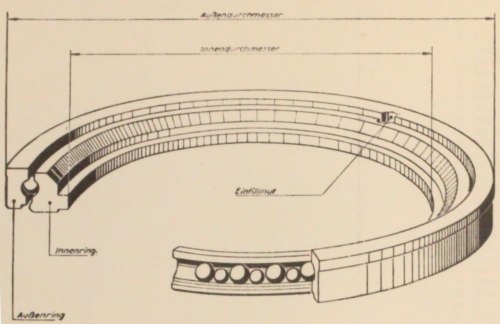
This diagram, extracted from a manual [3, see plate 65] , represents the ball-bearing race. Ball bearings are trapped between two concentric steel rings. The overall diameter ("Außendurchmesser") is 2100mm.
Ball bearings
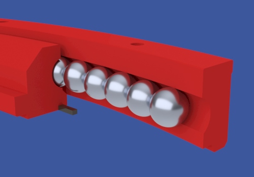
The original design used 158 ball-bearings, their centers lying on a circle of 1990mm diameter. Every second ball was load-bearing [1] with diameter 40mm. Alternating between them were spacer balls of diameter 39mm [3, see page 9] . The ball race was "crowded", with very little space between balls.
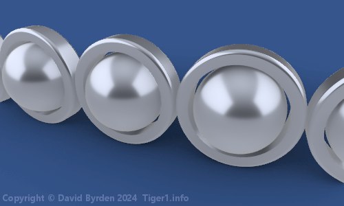
A "new" turret was introduced on Tiger 250391 in July 1943 [2, see page 81] . It introduced many changes, including a redesign of the ball bearing race. There were now 113 load-bearing balls, each one carrying a loose ring of 55mm diameter [3, see page 9] . Trapped in the vertical alignment by the ball races, these rings kept the balls evenly spaced. Also, the balls were moved slightly outwards, so that they now lay on a circle of diameter 1995mm.
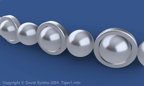
Although we have not found documentation about it, there was apparently a third and final arrangement of ball bearings. The preserved Tiger at Saumur Museum has it. In this case, there is a ring on every second ball. The number of load-bearing balls is now 130.
Bearing race rings
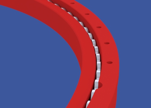
The ball bearings were trapped between two concentric steel rings. It was German practice to use not an upper and lower ring, but an inner and outer ring, because tank turrets were subject to lateral impact forces. This model shows the assembled ball bearing race. It's the final version, which is the simplest version.
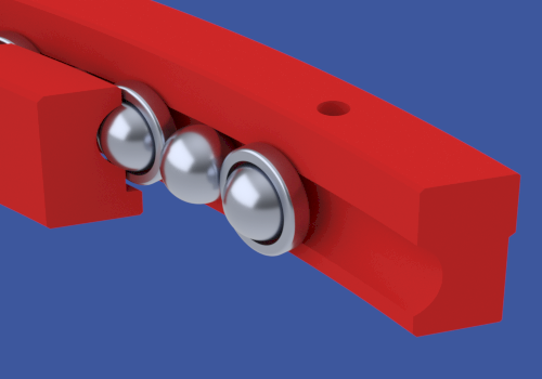
This is a cutaway of the mechanism. The spacer rings fit loosely in the gap between the bearing rings.

The outer bearing ring was attached to the turret, and the inner one to the hull. They each had a pattern of bolt holes drilled into them for this purpose. The holes in the inner ring formed a uniform symmetric pattern, but in the outer ring, as this image shows, there were some gaps in the sequence of bolt holes. Equipment in the turret made it impossible to use those positions. The upper ring therefore attached to the turret in only one orientation.
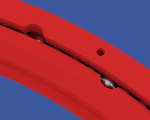
When assembling the bearing system you drop the balls in through a hole. This hole is formed by rotating the bearing rings until two notches align. They are both visible in this model. The notches are not aligned when the turret is pointing directly forward. The outer ring's notch was located 45 degrees to the right (1:30 o'clock). I don't know if the inner ring's notch had a mandated position. I have modelled it as found in the Saumur Tiger during restoration, but that turret may have been attached wrongly.