About this detail of the Tiger
The drive shaft in a Tiger I ran from the engine in the rear to the main gearbox in the front. Directly under the turret, it passed through a complex assembly that served at least three purposes; to pass mechanical power to the turret, to pass electrical power to the turret, and to pump water from the hull bottom.
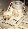
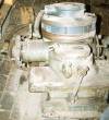
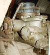
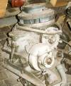
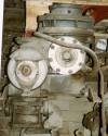
I have not yet managed to draw this assembly, and no German drawings have yet come my way, so here are my own photographs of the assembly from the Bovington vehicle.
You can purchase a coloured German diagram (reproduction) from Bovington museum, showing this assembly and what is normally attached to it. Go to page 10 of the Photo Gallery in the Tiger Tank Journal.
This photo shows the assembly, viewed from front right, after restoration by the Museum staff. It is bolted to its own attachment points on the hull's floor stiffeners; I've drawn a diagram relating them to the rest of the tank. The assembly was required to be dead centre under the turret, so the bolts allowed for some adjustment.
These photos show the right, back and left sides of the assembly respectively. It lies at an angle on the floor of the Museum workshop, before restoration. It has its original colours of standard interior blue-grey and a much darker colour that might be black or dark grey. It is very dusty.
A drive shaft, not shown in this picture, led directly from the engine to the round plate at the back. This plate was internally connected to the similar plate at the front of the assembly. Another drive shaft could be bolted to the front plate, this one taking power forward to the main gearbox. As far as I know, power went directly through this assembly without being tapped or geared in any way.
A smaller drive shaft took power from the main gearbox back to this assembly, this shaft was fixed to the small round plate that you can see in the first photo above, close to the camera.
Within this assembly, the returned power was brought out at the top centre, as you can see in the second photo above. The turret's hydraulic drive unit would connect with this point when the turret was lowered into place.
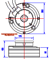
At the top of the assembly you can see a large fixed cylindrical head, and on top of that a smaller cylinder that is free to rotate; an electical cable emerges from it. This cable's usual place in the Tiger was that it ran along the turret floor under a protective duct. I have completed a diagram of this part, and it is reproduced above.
The large cylindrical head was a sealed unit containing metal rings and bushings that pressed against them. As the smaller part rotated, these bushings maintained permanent contact with at least some of the rings. This allowed several different electrical circuits to be maintained permanently between the hull and turret despite its rotation; I don't know yet how many circuits were available but I know there were likely to be some spares for future expansion. The large size of this unit is partially accounted for by the fact that the mechanical drive shaft had to pass through the middle.
In later Tigers we see that this topmost movable component was redesigned with a taper, probably to help alignment when the turret was being lowered over it.
The early Tiger I had underwater travel capability, but leaks were inevitable. There is a bilge pump underneath this assembly to deal with them, as you can see in these photos. It retains some of its red primer, that is, the manufacturer did not bother to paint it all. The return drive shaft could be used to power either the turret traverse or this bilge pump.
The pump sent unwanted water back through a pipe along the hull floor, this pipe eventually rising up the right-hand front side of the firewall and venting into the right-hand radiator compartment.
[1] Survey of Tiger 250122, at Bovington museum, by David Byrden
