About this detail of the Tiger
Rotation of the Tiger's turret was driven by the engine and controlled by a gearbox on the turret floor.
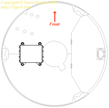
This diagram shows the location of the gearbox on the turret floor.
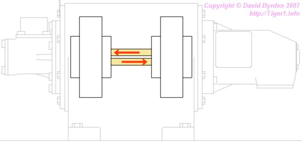
The gearbox was hydraulic, using oil as the fluid. The bottom of the casing was the oil reservoir. The upper casing was divided in two by an internal wall. There was an oil pump in one side, and an oil motor in the other side.
The input shaft drove the pump, which drove the motor via two oil channels in the wall. The motor drove the output shaft. This diagram shows the positions of the pump and motor, and the oil channels.
Oil was pumped into the motor through one channel, and back again through the other. The direction of flow depended on the direction of turn of the turret.
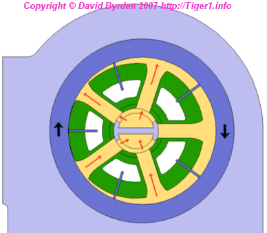
The pump and motor were physically identical; the motor was effectively a pump driven in reverse. They were rigid-vane type pumps [1] . In this sort of pump, a wheel rotates in a housing. Vanes in the wheel press against the housing and divide the space into moving compartments. As the wheel rotates, the compartments grow larger or smaller depending on their position. This can be used to pump fluid.
I don't have complete German drawings of the vanes and housing, so I don't know how many vanes there were. But this diagram shows the most likely number. The green wheel is linked directly to a drive shaft. The central axle, with its two oil channels, does not rotate. The vanes are gripped by rings in the housing so they slide in and out without springs. The housing itself rotates.
It is obvious that the efficiency of the pump depends on how far the housing is off-center. The maximum displacement in the Tiger seems to be 6mm. Also, because there are two channels, the direction of flow can be selected by moving the housing either to the left or the right.
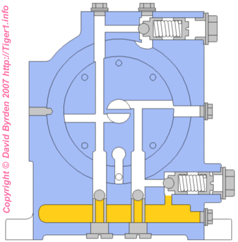
This is a section through the central wall. The wall was removable, being made of circular inserts. The oil channels are visible here, as well as various other channels that are drilled in the wall and sealed up with screws. Oil is shown in the reservoir; the screw at bottom right was for emptying it. During operation, all these channels would fill with oil.
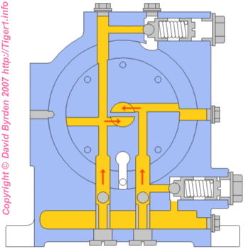
If the turret were turned by hand, the oil motor would suck oil from the channels. One of the non-return valves in the bottom of the wall would open, as shown here, providing a free flow of oil so that the turret could be turned. The pump was self-priming (i.e. it would suck oil into itself when started up) thanks to these valves.
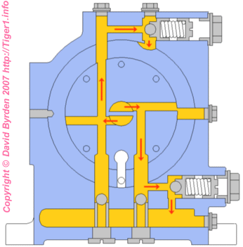
If the turret became stuck on an obstacle while the gunner was turning it, the pump would raise the oil pressure in the system. One of the spring-loaded safety vales would open, as shown here, and allow oil to flow back to the reservoir.
[2] Tigerfibel (user's guide for the Tiger 1)
[4] Survey of vehicle 251114, at Saumur, by Jean-Charles Breucque
[5] Survey of Tiger 250122, at Bovington museum, by David Byrden