About this detail of the Tiger
The turret shape brought the side walls together at a slight angle. The gaps between these walls and the gun mantlet were filled with carefully shaped mountings.
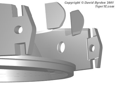
After boring various holes in the armour pieces, the manufacturers welded them together. The picture above shows the mountings and their locations on the turret side walls. As you can see, trenches 5mm deep were cut into the wall to seat them. The front of these trenches could be seen from outside the vehicle if the gun were removed. A good photograph is in "Tiger Tank: A British View", page 47.
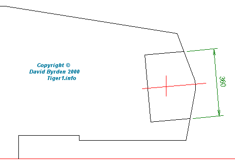
The diagram above shows the size of the trenches, which were tilted by 5 degrees to match the slant of the frontal turret armour.
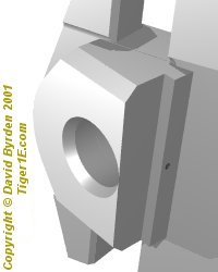
Holes had to be bored right through the mountings to hold the trunnions. I don't know the complete fabrication sequence of the turret but I would expect the pieces to be welded into place before they were bored. The picture above shows the final appearance of one, except that I haven't added the weld. Notice that it has a small hole at the rear, through which lubrication grease was fed to the gun bearing.
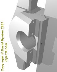
The shape of the mountings was slightly different in the early and late-model turrets. To make room for the waterproofing system, deep notches were cut into the early-model pieces. The picture above shows the right-hand cheek in the early-model turret. As well as having this large notch, the rear of the piece is different between early and late models. All of the diagrams below show the early model.
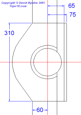
This diagram shows the size of a mounting and how it fit with the 100mm armour pieces above and below it. Note that the gun axle is not exactly in the middle of the 100mm front armour plate; it is set 60mm back.
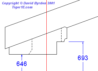
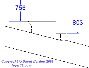
These diagrams show where the mountings were located relative to the center line of the turret and gun. Notice that the left side is 110mm wider than the right. Note also that, due to the asymmetry of the turret, the pieces have different shapes.
[1] Factory drawing 2AKF31861U1B11: Turmgehause (overall turret armour)