About this detail of the Tiger

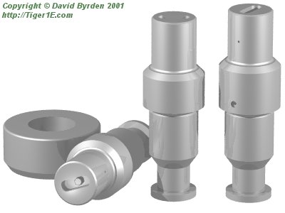
The items in the picture above fulfilled the following 3 functions in the Tiger 1; allowing the turret to be lifted; supporting the gun's weight and recoil; and lubricating the gun bearings.

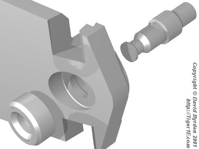
Holes were bored through the armoured walls of the turret and the cheek pieces, and these cylindrical steel rods were threaded through them as shown above. A wider hole was cut for the ring to seat it firmly.

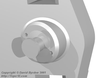
The outer ends of the rods formed lifting points for the turret as you can see in this picture. Due to the asymmetry of the turret, the left and right rods had different lengths; you can see the difference in the picture at the top of the page.

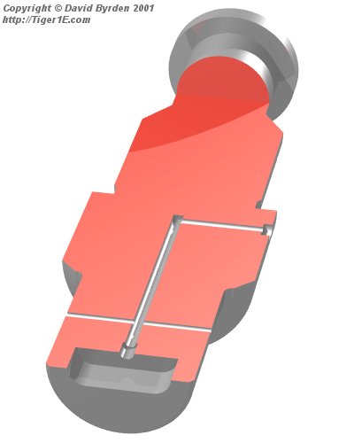
This picture shows one of the solid rods artificially sliced open.
The inner ends of the rods served as the trunnions for the gun, and carried spherical gun bearings. To lubricate these bearings, which were quite inaccessible, channels were drilled through the rods as shown above. Lubricating grease was fed into the back of a cheek piece, which led it to the channel at the widest part of the rod. It was then guided to 2 exit holes where the surface of the rod met the gun bearing.
The exit hole at the end of the rod was not part of this scheme; it was simply an artefact of drilling the channels. Therefore it was threaded and sealed up with a bolt (not shown). The large oval hole at the end of the rod served to keep this bolt out of the way, and allowed it to be installed by finger.
[2] Factory drawing 2AKF31861U1B11: Turmgehause (overall turret armour)