The Tiger's engine could be started by a hand crank lever, or by a shaft driven by a "Kubelwagen" motor. In both cases, the shaft was inserted through a hole in the back wall of the Tiger, and connected to a gear wheel on the engine.

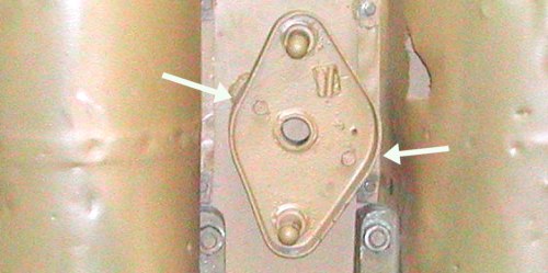
To stabilise the shaft and line it up with the engine, this adaptor plate was inserted into the rear wall. The drive shaft passed through the hole in the middle of it. (Later versions of Tiger had a different engine and their adaptors had two holes.) The posts at the extreme corners of the plate were used to align motor-driven shafts.
When not in use (which was most of the time), this adaptor plate was stored on the rear wall of the Tiger. It had two locking hooks (which I pointed out) that could be turned with a wrench.

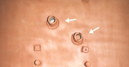
This is the bare wall of a Tiger, which bears two hollow tubes for the adaptor plate. The hooks on the plate slide into these tubes and are locked by rotating them.
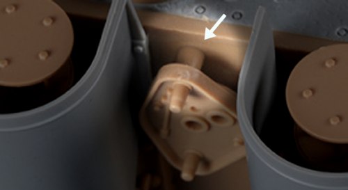
These posts are positioned such that the adaptor plate will be vertical, as the first photo shows.

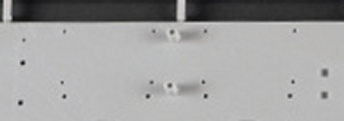
Trumpeter have made an error here. They lined up their tubes with the outer posts of the adaptor, instead of the locking hooks.

This is the kit's back wall; compare it to the real one pictured earlier. I think it would be relatively easy to correct this by slicing off these tubes and gluing them to the back of the adaptor plate, to guarantee the correct spacing and angle.