About this detail of the Tiger
The Tiger's HL 210 engine had an inertial starter on its forward right corner. It was driven via a shaft and a chain from a gear wheel at the center rear of the engine.
After using a handle or a motor to spin up the starter, the crewman would connect it to the flywheel by pulling a lever at the back of the engine.
In the original design of the Tiger, it was necessary to remove the starter handle and adapter plate in order to reach this lever.
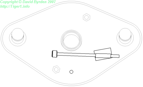
Photographs suggest that sometime after November 1942, an improvement was made. A tool was added to the adapter plate, as shown here. The tool was stored in a sleeve and also secured by a chain (not shown). The crewman would take this tool from its holder and poke it through the small hole near the bottom of the adapter.
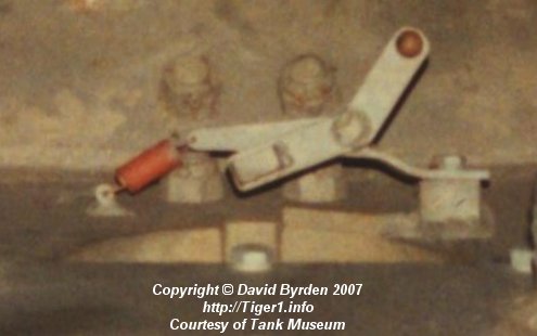
Here, we are looking down at the inside of the starter port in the Tiger at Bovington museum. The tool would push the small block in the center of the photo, turning the spring-loaded lever clockwise. The other end of the lever was connected to the clutch control on the engine.
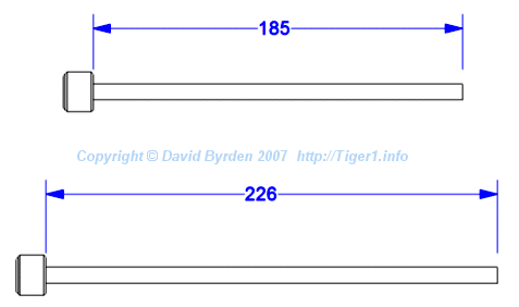
The tool was made 41mm longer from the 101st Tiger onwards [4, see 3.4.1.1] .
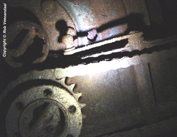
In May 1943, the Tiger's engine was changed to the HL 230 [4] . The clutch control was in a different position on the new engine. This photo shows a rusting Tiger in Saumur museum. The clutch control is the lever in the center; its axle is at the right. The drive wheel for the starter is at at bottom left.
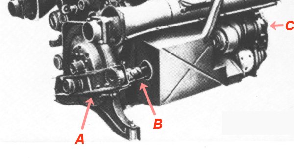
In this German photo, the clutch lever is at [A]. It pulls a rod at [B] that passes through a tunnel in the oil tank. The inertia starter is at [C]
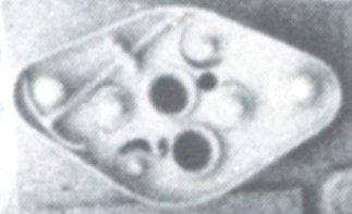
The adapter plate was redesigned with a new tool, as seen in this detail from a wartime photo. The small hole to the right of center is for the new tool. It is directly in line with the clutch control lever.
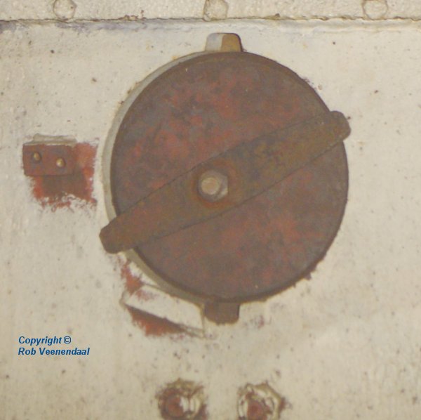
A new, simpler mechanism was designed for the new engine. This is the inside of the Sturmtiger preserved at Munster museum. The lever under the starter port is gone; instead, there is a welded mount to the side.
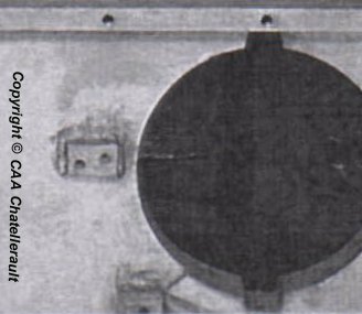
This hull was completed about June 1943 [1] . It is transitional, with mounts for both the old and new mechanisms .
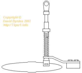
The new mounting point was for an arm carrying a spring-loaded rod. This diagram looks down from above. The arm and the rod are shown; the forward end of the rod would be connected to the lever on the back of the engine. The crewman would lock the tool into the rear end of the rod, and pull.
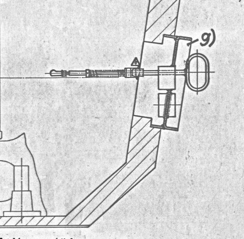
This German diagram [6] shows the tool passing through the adapter plate and locked into the spring-loaded rod.
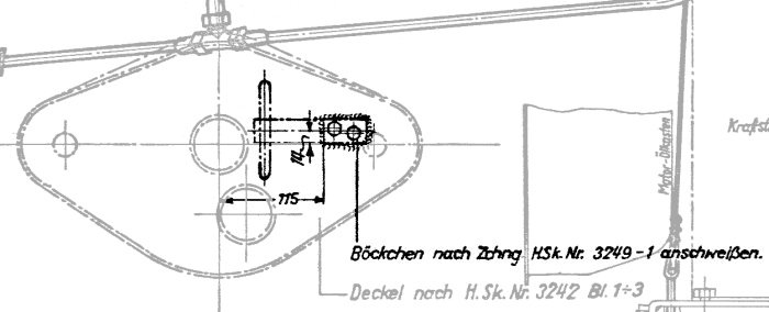
Here is another detail from the same diagram. It looks from the rear, showing the adapter plate, the tool and the arm. The legend specifies how to install the arm.
[1] German report on experimental ventilation gear for Tiger 1, now at Chatellerault archive
[2] Survey of Tiger 250122, at Bovington museum, by David Byrden
[3] Survey of Sturmtiger at Panzermuseum Munster, by Rob Veenendaal
[4] DW to Tiger 1
[5] Survey of Tiger 251114, at Panzermuseum Munster, by Rob Veenendaal