About this detail of the Tiger
The four torsion bars for the front and back wheels of the Tiger I were thicker than the rest, and their swing arms were equipped with shock absorbers internal to the hull. These shock absorbers consisted of an arm that pushed a plate through an oil-filled tube. The arm could move a distance of 160mm.
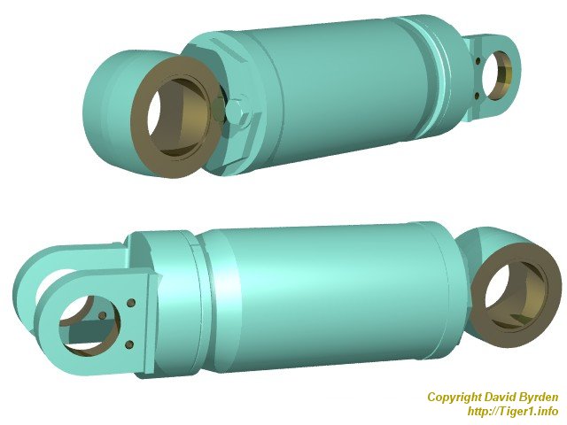
Here are two views of a model of a shock absorber. It's called a HT90 and was also used in Panther tanks. The upper view shows the end of the moving arm, which was fixed to the Tiger's hull wall. In the middle is the tube containing the damping oil. The capacity was 1750cc and the whole thing weighed 23.4kg. At the other end is a bronze mounting that attaches to a radius arm, which is itself fixed to a suspension swing-arm.
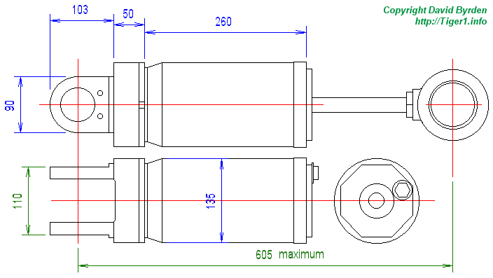
These are my diagrams of the HT90, based on a German original. Green dimensions are German specs, blue ones were measured from vehicles.
As stated in the Driver's Manual [3, see B. 10. d)] : "The shock absorbers are one-way, they dampen the downward movement of the swing arm. One-way damping is achieved by a one-way valve. During upward motion of the swing arm, the shock absorber cylinder is pushed upward without resistance. Shock absorber oil in the cylinder pushes through the valve in the shock absorber piston to the other side without hindrance. When the swing arm goes down again, then shock absorber oil is squeezed through a small hole in the valve (the throttle point) and damping occurs."
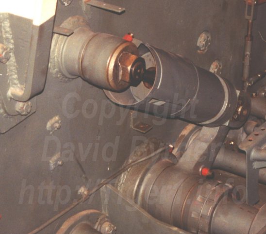
This is the front left shock absorber in the Tiger at Bovington Museum. At the top of the photo, we can see how the moving arm is fixed to an axle embedded in the hull wall. The exposed part of the arm is protected by a sheet-metal sleeve so that the driver's clothing will not get caught in it.
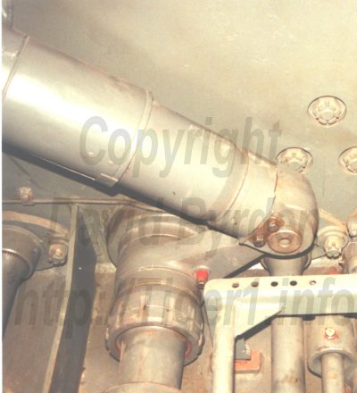
The lower end of that same shock absorber is fixed to an arm that is attached to the inner end of the foremost swing arm on that side. At bottom right of the photo we can see the frame that supported the driver's seat.
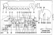
In the photos above, you can see two grease lubrication taps on the shock absorber; one for the axle at the upper end, and one in the swing arm, which leads the grease via internal channels to the bottom of the shock absorber and also to the bearing for the torsion bar. This is the Tiger Lubrication Chart. It states that shock absorbers should be refilled with grease every 250 km. The two lubrication taps on the front left arm are numbered (3). The rear arms were inside the engine compartment and were greased via the rear batteries of lubrication taps. The diagram also states: "when the engine is removed, check the oil level in the front and rear shock absorbers and add the special oil."
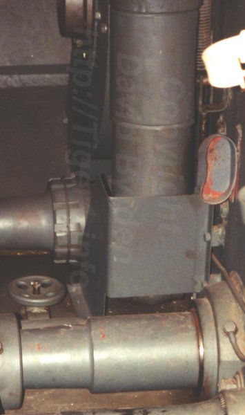
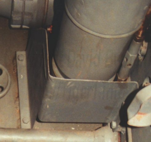
The shock absorber at front right was protected by a fairing fixed to the hull. Presumably there was a danger that it would crush the crewman's foot.
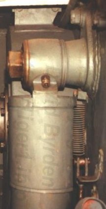
This photo of the top end of that shock absorber, clearly shows how it is attached to the fixed axle.
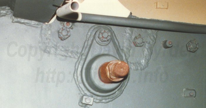
The axle for the right-hand shock absorber was, for some unknown reason, attached to one of the foremost bolts holding the sponsons to the hull. No other axle had this shape.
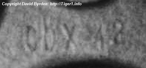
A close look at this casting reveals a legend.
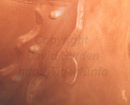
This is the same axle, seen from outside the hull. Only a flat raised disc is visible. The bolts in the flange have flat conical heads and are hardly visible.
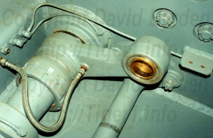
This is the swing arm for the rear right shock absorber, which was removed during the restoration of this Tiger. It is just behind the firewall. Notice the bronze bearing and its internal lubrication channels.
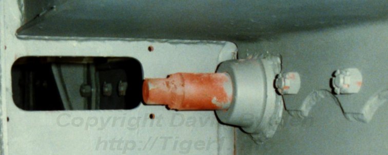
The axles for the rear shock absorbers were flattened on top, so they could sit close to the sponsons.
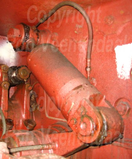
In the Sturmtiger at Munster museum, we find the complete rear left shock absorber. Notice how close it sits to the idler wheel tensioning arm. The shock absorbers in the engine room didn't have the sheet-metal sleeves.
[1] Survey of Tiger 250122, at Bovington museum, by David Byrden
[2] Workshop drawing 700/0434 (HT90 damper for Panther and Tiger)
[3] Panzerkampfwagen Tiger Ausführung E ; Driver's Handbook ; D 656/23
