About this detail of the Tiger
The radiator compartments in the Tiger were designed to be floodable. The engine, of course, could not be flooded because its heat would generate steam. The engine compartment was therefore surrounded with waterproof seals on all sides except the front, where it met the crew compartment.
The upper sides of the engine compartment were thin 8mm steel walls. On top of them a solid steel frame was welded, providing strength and allowing the engine compartment door to form a waterproof seal.

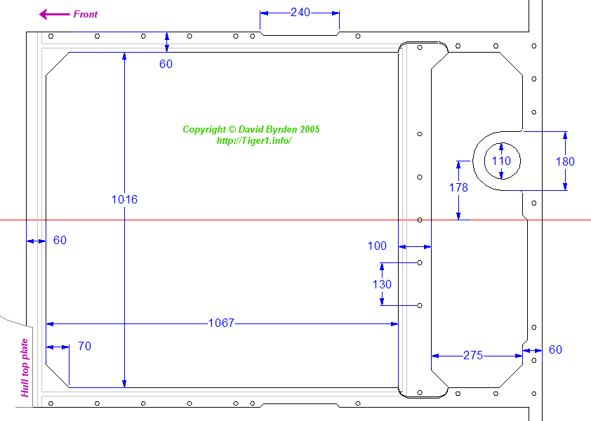
This is a diagram of the frame as seen from above. Its front edge (on the left of the diagam) tucks under the hull top plate, which was nominally 25mm thick.

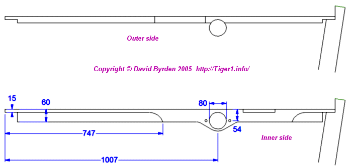
The central crossbar was removable and indeed it had to be removed in order to lift out the engine. The form of this crossbar is a thick flat plate with a hollow spar of thin steel underneath it to add strength. When the engine was changed from HL210 to HL230, this crossbar was found to be too deep. Field units upgrading tanks to the new engine were instructed to cut off the bottom 15mm of the crossbar. This would open up the hollow spar. There must have been a new design of crossbar for new tanks, but I have no record of it.

At the rear of the metal frame you can see a round projection. This anchors the end of a tube for disposing of hot air from the exhaust cooling system. This air was normally dumped into the outlet fans, but when underwater it was released into the engine compartment by an outlet in the side of this tube. On top of the engine deck, the top of this tube was accessible through a large screw cap, like those over the radiators and upper fuel tanks. I don't know the reason for this system; perhaps they planned to provide a non-return air valve at that point and get rid of the hot air that way? In any case, they must have changed their minds, because while Tiger #250031 has the screw cap, on Tiger #250122 the cap is welded into the engine cover to seal it off crudely.

The frame is 60mm deep and up to 60mm wide. You can see that it is stronger at the rear, to support the open hatch. Pipes leading hot water to the radiators are abutted to holes drilled right through the thickest part.

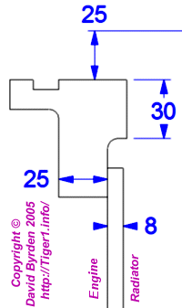
This is a profile of the frame near the forward end. You can see how it is welded on top of the 8mm wall. The frame is 25mm below the top level of the hull roof, but there are cast grilles in this area with different thicknesses which I have not drawn. You can also see the gutter in the top of the frame.
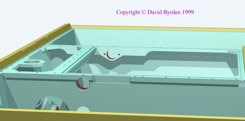
The following model shows the layout of the frame clearly. It also shows the flat duct that guided hot air from the cooling system into the main fans. The exhaust pipes from the engine ran through the large holes; the bottom holes were sealed by a flat plate and were for maintenance, allowing you to drain any water that might get in; and the top holes were connected to the fan drive by tubes that I have not modelled yet. See them on this diagram in Tigerfibel:

In the middle of the rear wall there are mounting points for the early fan drive gearbox.
The above diagram gives the positions of the bolt holes in the frame, as initially designed. At some point during the history of the Tiger, one of these bolt holes was moved. It was at the inside rear corner of the radiator cover. I don't know when this move happened.

[1] Survey of Tiger 250122, at Bovington museum, by David Byrden


