The crew flooring in the Tiger's hull was made of removable panels in a skeleton framework.
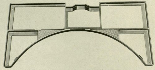
This is the framework ahead of the turret; there was a smaller frame behind it. Floor panels sit in these openings. [1]
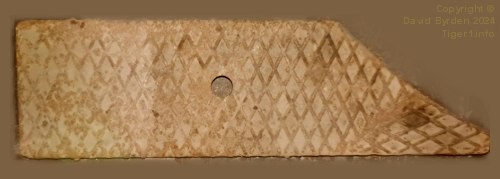
This is one of the rear panels. It has a central finger hole so that it can be pulled out. The panels weigh several kilograms each [1] .
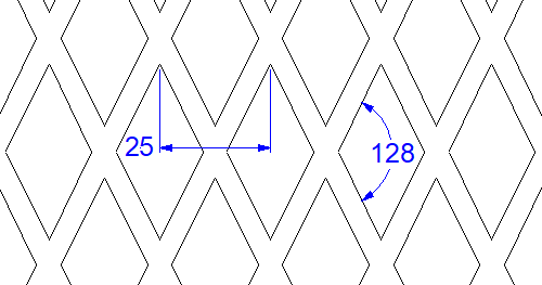
The surface of the panels has this raised grid pattern. The factory workers were free to align it laterally or longitudinally on each panel, it didn't matter. One panel in Tiger "131" comprises two fragments welded together.
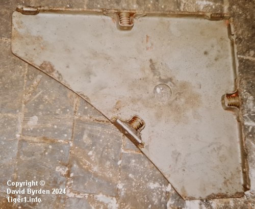
Panels were locked into the framework by spring-loaded plungers on their undersides.
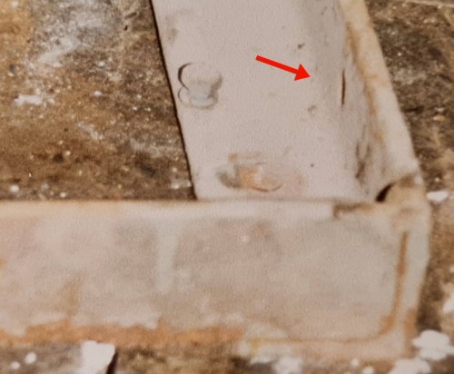
These plungers engaged with holes in the inner sides of the frames.
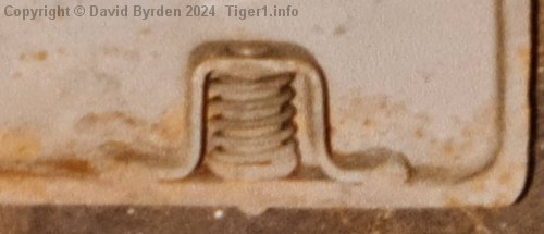
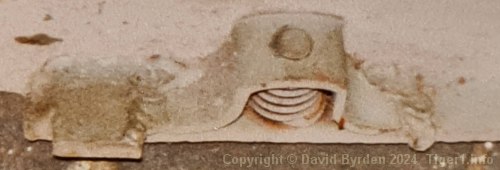
Note also the welded square; these squares set the height of the floor panels at 5mm below the top edge of the frames.
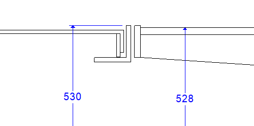
This profile shows some of the fixed flooring at the left, and the edge of the turret floor at the right. A German diagram specifies that the turret floor surface is 528mm above the hull bottom plate [3] . This is consistent with my calculations that the top of the flooring framework is 530mm high. The floor panels themselves are therefore at about 525mm.
[1] Kraftfahrgerät teil 3, Fahrgestell und Turm Panzerkampfwagen "Tiger", heft 60
[2] Survey of Tiger 250122, at Bovington museum, by David Byrden
[3] Drawing J3154 : "Einbau des ZF. 12 Gang Elektro Getriebe."