About this detail of the Tiger
The prototype designs for the Tiger gave it 3 rows of roadwheels, the wheels in the central row having 2 tyres. According to the Driver's Manual;
"The road wheels are nested (Boxed Running Gear) and intertwine as interior and exterior road wheels. The pairs of interior road wheels are enveloped by the pairs of exterior road wheels."
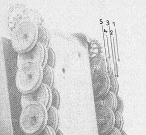
But the great weight of the vehicle necessitated wider tracks. To each axle, a flange and an extra wheel were added. This made for 5 rows of wheels, as this diagram from the Tiger Fibel [5, see page 36] shows. The extra wheels and the wide tracks had to be removed to bring the vehicle within rail transport limits. According to the Driver's Manual;
"Due to widening of the track, interior and exterior wheels were augmented with one auxiliary wheel each, on the outside. These are removed when applying the narrow shipping track."
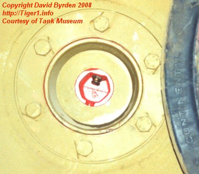
This photo of the Bovington vehicle under restoration [2] shows the wheel in row 2. At the center is the lubrication tap for the hub.
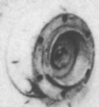
When the wheel is removed, it reveals the 'inner flange' (detail from a British wartime photo of the same tank) [1, see page 103] . This flange is bolted to another hidden flange, the bolts passing through the wheel in row 3. Notice that the bolts of the wheels in rows 2 and 3 are anti-aligned.
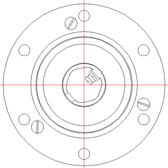
This diagram shows the face of the inner flange, as in the photo. The flange consists of 2 parts; a spacer and an internal ring. As directed in the Tiger Hull Manual [4, see B. 10. b) ] , the ring is not removed when transporting the vehicle; "The internal ring fastened with 3 countersunk screws remains at the hub of the exterior road wheel." [1]
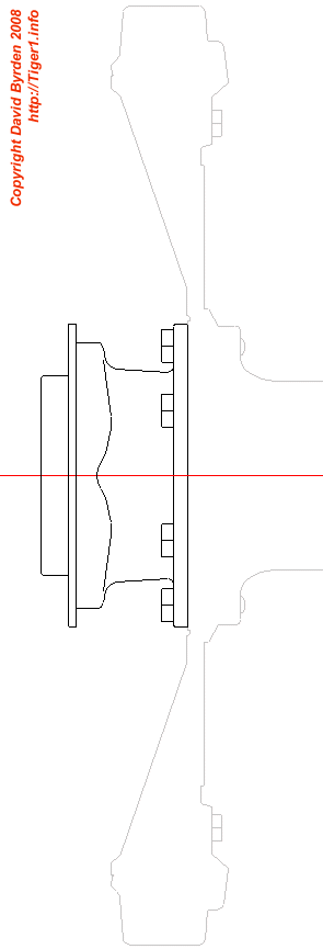
This profile shows the flange attached to the row 3 wheel, in shipping configuration. The outer face is to the left.
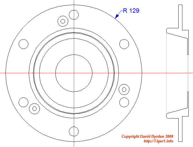
This is the 'internal ring' removed from the flange. Its helps to seat the wheel, and keeps debris away from the swing arm.
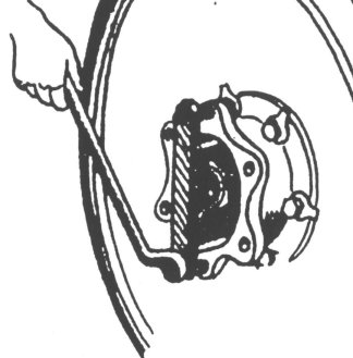
This German diagram from the Tiger Fibel [5, see page 37] shows a mechanic removing the main part of the flange. He has already removed the 'internal ring' so that he can insert a tool, the "Abziehvorrichtung für Außenradflansch" (puller for the outer wheel flange). By tightening the M12 forcing screws in the tool, he can pull the flange off the swing arm. But first he must remove the 6 bolts linking the flange to the wheel behind it.
The Tiger Fibel lists the tools required for this job: tool '27' (a standard wrench), tool "2798 U10" (illustrated above) and a screwdriver. [5, see page 36]
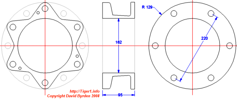
This is the main part of the flange, with the internal ring removed. The outer side is star-shaped, with gaps that allow the removal of bolts from the wheel in row 3.
[1] DW to Tiger 1
[2] Survey of Tiger 250122, at Bovington museum, by David Byrden
[3] Survey of Tiger 250122, at Bovington, by John Desaleux Survey by John Desaleux of Tiger 250112, at Bovington Museum
[4] Panzerkampfwagen Tiger Ausführung E ; Driver's Handbook ; D 656/23