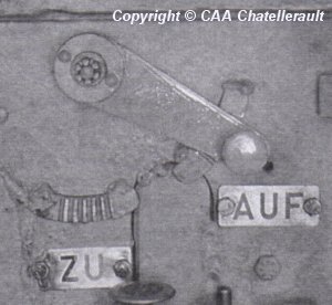
About this detail of the Tiger
This diagram [4, see page 23] shows the flow of cooling air in a Tiger 1. Hot air from the gearbox cover was blown over the exhaust pipes to gather more heat, then into a box on the rear wall of the vehicle. From there the main fans sucked it through pipes into the fan ducts.
During underwater travel, the main fans did not work and the sponsons were flooded. Air flow had to be redirected. As the diagram shows, there were butterfly valves ("Drosselklappe") in the pipes leading from the box to the sponsons. These were normally kept open. Also, a vertical pipe going upwards from the box had a valve near the top. This valve was normally kept closed.
Before underwater travel, all these valves were switched. The hot air then entered the engine compartment from the vertical pipe.

All three valves were controlled by a handle on the front left of the firewall. This photo [5] shows the handle in a tank built in mid 1943. Two curved bars with teeth are welded to the firewall; the handle clicks into these teeth and they hold it in position. (The air vent has been sealed up because experimental equipment is installed in this vehicle.)
The Tigerfibel states [4, see page 21] that this handle "leads the hot engine air to the fans or into the engine room". The positions of the handle are here marked "Zu" and "Auf". But in the earlier vehicle at Bovington museum [2] , there were hand-written words on the firewall: "Landfahrt" and "Wasserfahrt", meaning "Land travel" and "Water travel" respectively.
[1] Survey of Sturmtiger at Panzermuseum Munster, by Rob Veenendaal
[2] Survey of Tiger 250122, at Bovington museum, by David Byrden
[3] DW to Tiger 1
[4] Tigerfibel (user's guide for the Tiger 1)
[5] German report on experimental ventilation gear for Tiger 1, now at Chatellerault archive
