Fuel in the Tiger was fed to the engine by pumps. These pumps were attached to the engine and driven mechanically, by a rotating shaft inside the crankcase (which also drove the oil pumps).
Two engines were used in the Tiger, at first the HL210 and later the HL230. Their respective pump systems were slightly different. Also, there was an electric primer pump in Tigers equipped with the HL210, whereas the HL230 was primed manually.
HL210 fuel pumps
This engine had a battery of four pumps.
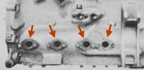
I have pointed out four small holes on the left side of the engine's crankcase. The four pumps attach to them.
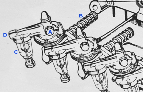
This illustration is from a large and highly detailed diagram of the HL210, drawn up by British analysts. It shows the four fuel pumps separated from the engine and disconnected from the fuel lines. I have annotated one of the pumps.
Fuel is drawn in through a connector at [D]. It passes through a filter that deposits debris into a glass sediment bowl [C]. The bowl can be unscrewed and removed for emptying. These are secondary filters; elsewhere in the Tiger there was a main fuel filter.
Fuel is then sucked into the round flat housing below [A]. The pumping mechanism is a membrane inside this housing. Fuel is finally pumped out through the connector at [A] or a matching one on the other side of the head.
The spring-loaded plunger [B] passes through the hole in the crankcase, and gets pushed by a cam on the rotating shaft. The cams are angled so as to operate the four pumps in a sequence.
The fuel pumps on Tiger "712", now in the USA, were intact and in good condition when its restoration commenced. There are clear photographs of them in Lloyd, Balkwill, Johnson [1] .
HL230 fuel pumps
The HL230 engine had only two pumps, but each one had two of the membrane housings so that it was effectively a pair of pumps. They shared a fuel inlet, outlet and filter, thus the new system was less bulky than the old. As another benefit, the crankcase needed only two holes.

Here is the forward bottom corner of a HL230. I have pointed out the two pump units connected to it. Notice that the round housings containing the pump membranes are now oriented vertically, and each unit has two of them. The fuel inlet line, which splits into two branches, is under the pumps; the pipes running upward are the carburettor lines.
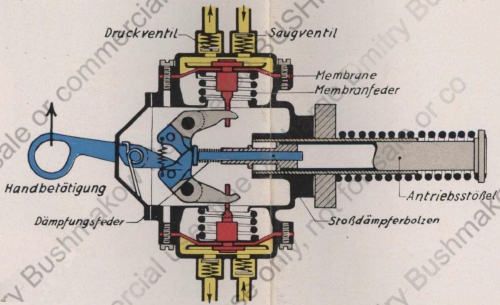
This schematic of a HL230 pump unit is provided in a German manual [2, see Bild 14] . The spring-loaded plunger is on the right, and the sketch shows it passing through the crankcase wall, though the rotating shaft is not illustrated. Each push causes the two blue hinges to close the two grey arms, moving the red membranes back and forth. Each membrane moves fuel (yellow) from an inlet to an outlet, both of which have the appropriate one-way valves. The large lever allows hand operation of the pump.
German descriptions
This is a brief description of the HL210 fuel pumps, translated from a manual [3] ;
The fuel pumps deliver fuel from the fuel tank to the carburettor. The pumps are actuated by a cam on the oil pump drive shaft. The cam presses directly on the pump's plunger.
The pump's delivery rate automatically adjusts to the carburettor's fuel requirements. A sufficient amount of fuel is always delivered, but never more than necessary. The fuel pump consists of an upper and a lower section. The plunger mechanism is located in the lower section. The upper section, designed as the pump chamber, contains the suction and pressure valves. When the diaphragm moves downward, fuel is drawn into the pump chamber through the suction valve. During the plunger's return stroke, a spring pushes the diaphragm upward, forcing fuel through the pressure valve into the carburettor line.
A fuel filter is installed upstream of the fuel pump and is attached to the upper section of the pump. Impurities are retained in the plate filter and settle in the filter bowl.
This is how the Driver's Manual of 1944 [2] explains the HL230 fuel pumps;
Fuel is delivered to the carburettors by two Solex twin-pushrod pumps.
Each twin pump consists of two diaphragm pumps combined in a single pump housing with a common plunger drive. Each individual pump draws fuel from a common suction line via a suction valve and delivers it to the common pressure line via a pressure valve. A fuel filter with a filter housing is installed upstream of each fuel pump. The fuel pumps are driven by cams on the oil pump shaft.
During the suction stroke, the diaphragms are pulled inwards by the drive via bell cranks. The pressure stroke is achieved solely by the action of the diaphragm spring, whose tension determines the pressure in the line. When the carburettor is full and the float needle valve is closed, the diaphragm spring can no longer overcome the back pressure in the pressure line, and the diaphragm remains retracted. The bell crank no longer follows the return movement of the drive plunger, and the fuel pump runs dry. In this process, the shock absorber bolt remains in contact with the angle levers under the influence of the damping spring, its shaft sliding in the guide bushing of the tappet.
The pumps are equipped with a manual override for filling the lines and carburettors before starting the engine. This is accessible after removing the cover on the bulkhead. Both pumps must always be operated simultaneously.
The fuel pump housings and filters must be cleaned every 500 km (310 miles). The pumps are accessible after opening the designated cover in the sump base. Removing the housings from the bulkhead is difficult and should be avoided due to the risk of damaging the seals.
Note:
When installing the housings, pay particular attention to ensuring the seals are properly seated. Leaking fuel poses a fire hazard and will prevent the pump from functioning correctly.
Access to the pumps
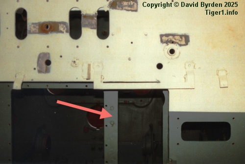
This is the firewall of Tiger "131" during restoration at the Tank Museum. Much equipment has been removed, allowing us to see the openings in the base of the firewall. I have pointed out the opening that gives access to the fuel pumps. It has a simple, easily removed metal cover.
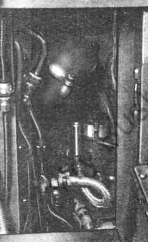
Behind the panel is this maze of pipes [3, see Abb. 31] . The HL210 engine is to the left of the image, and the bulbous item at the top of the image is its oil filter. The main fuel filter is to the right, connected by a reflective fuel line. The sediment bowls of the engine's four attached fuel pumps are out of sight, low down to our left. This opening is only 20cm wide [4] .
[1] A MODERN STUDY OF Fgst. Nr. 250031, by Lloyd, Balkwill and Johnson
[2] Panzerkampfwagen Tiger Ausführung E ; Driver's Handbook ; D 656/23
[3] D 656/21 "Panzerkampfwagen Tiger Ausführung E"
[4] Survey of Tiger 250122, at Bovington museum, by David Byrden