About this detail of the Tiger
The Tiger 1 had a firewall between the crew and the engine compartment, made of 10mm steel. It had several controls, openings and removable panels. This diagram shows the front side of the firewall. It had a large central recess to accomodate a fan.
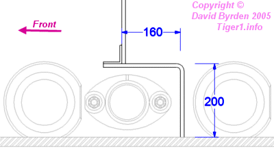
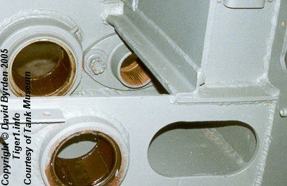
The bottom of the firewall was stepped so that it would fit between the torsion bars. The diagram and photo show the step on the right-hand side of the tank.
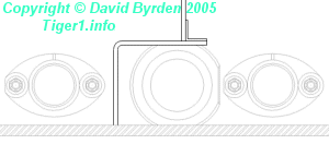
As far as I can tell, the torsion bar bearing on the left side had its top cut off so that it would fit under the left-hand step.
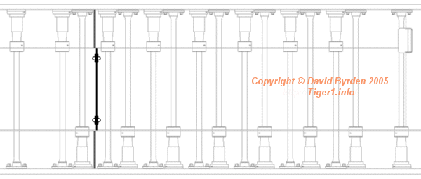
This diagram shows where the steps, and the central recess, met with the hull floor. There were only 3 torsion bars in the engine compartment.
This CAD model shows the rear of the firewall. The panels here are all removed except for the main panel that held the engine in place. There were two short tubes at the bottom to allow bilge water to be drained from the hull through the firewall.
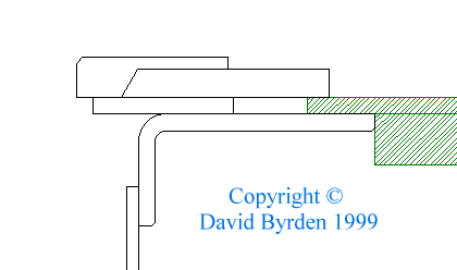
The top of the firewall was strengthened by an L-girder and a flat strip, both made of 15mm steel. You can see them in the cutaway model above.
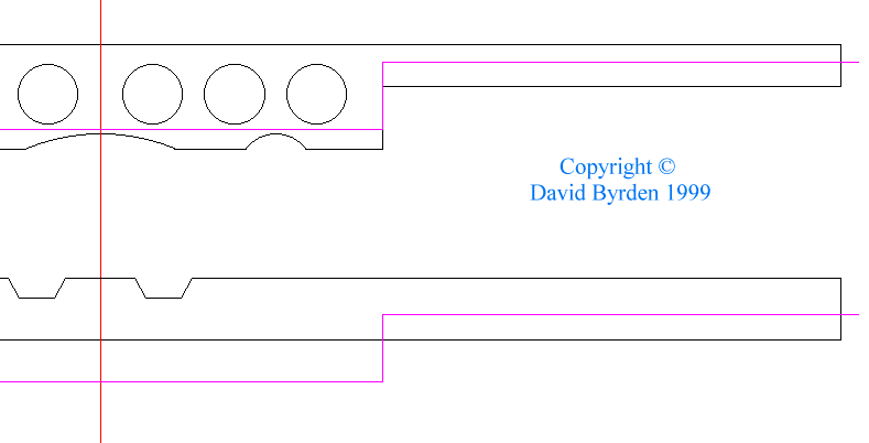
Their exact layout is shown in the diagram below. The engine cover support frame is shaded green in the diagram. It rested on a tongue protruding back from the L-plate, and this tongue had 12cm holes cut in it, apparently to save weight. These holes should be partially visible in your model if the roof can be removed, because of the gap between the flat plate and the frame. Note that parts of the flat strip, in the model above, are exposed and painted with the interior colour, in this case blue-grey. The grilles over the fuel tanks were bolted to these exposed surfaces.
The notches in the tongue were to make way for the locking handles of the engine cover plate. The diagram below shows the relation of all these features to the tail end of the hull roof (drawn in purple).
These pictures show the appearance of the top of the firewall on both sides. Not all of the attached equipment is in place:
[1] Survey of Tiger 250122, at Bovington museum, by David Byrden


