About this detail of the Tiger
The designers of the tank chassis that became the Tiger 1 (originally VK3601) made an interesting decision, possibly to save weight. The engine required a heavy cast-iron mount to support it at the rear, but at the front they mounted engine directly in the firewall separating the engine room from the crew compartment. In front of the engine they wanted to mount a large fan in a housing, to drive cooling air over the exhaust system. If the firewall were to directly support the engine, then this fan assembly, almost a meter wide, would have to be on the crew side of the firewall. But that would prevent them laying floor panels all the way to the firewall, and reduce the standing room for the crew.
The solution was to create a recess in the firewall, just deep enough (130mm) to contain the fan housings. The diagram above shows the opening as seen from the crew compartment looking backwards. You will note that the opening is slightly wider on the right-hand side of the diagram; this may be due to a late change in the engine design, as detailed later. On the floor you can see a slice through two longitudinal air ducts, the larger of which supplied the fan.
The recess was fully enclosed except at the front, by 8mm steel panels. Several holes were cut in the back panel; and you can see models of the whole thing elsewhere on this site. Below is a diagram of the back panel of the recess, again looking backwards. Notice that the recess is slightly larger than the hole in the main firewall; an exact fit was unnecessary, and in fact all bulkheads and cross members in the vehicle had to allow for the main armour plates being out of place by up to 5mm.
The vertical red axis lines mark the center of the vehicle and of the exhaust systems; so, on the outside rear hull of the Tiger, you would find the exhaust stacks to be 750mm apart. The holes in this interior bulkhead are aligned with those stacks, and I will suggest reasons later. The horizontal line 370mm above the floor marks the axis of the engine crankshaft. The hole is aligned with it because this hole serves as the front mounting for the engine itself.
There follows a profile of the recess, seen from the left of the vehicle looking right. At the top of the diagram, notice how the firewall is very close to the turret supporting ring on the hull top. Also note that there are two openings in the bottom of the recess, each with an inverted-U pipe (made of two halves) leading through it. I'm not sure what is the thinking behind them, but the basic laws of physics tell us how they work: fluid in the engine compartment can not rise to over 120mm deep, because these pipes then begin to drain it into the crew compartment, where the bilge pump can remove it and in fact pump it down to about 20mm deep. The fact that fluid is not introduced into the crew compartment until it reaches 120mm suggests that they did not want to expose the crew to fuel leaks, but while the vehicle was submerged they wanted the ability to remove leaking water before it would cause damage to the engine.
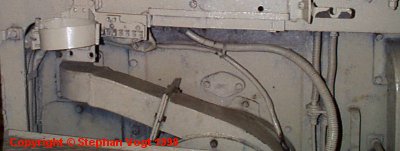
All of the holes in this wall were sealed in use. Unfortunately the sealing equipment from the Bovington vehicle was removed during its wartime British examination, and I never found it. Stephan Vogt makes up for my deficiency with these photos of the surviving "APG" Tiger 250012, whose current whereabouts are the subject of much speculation. The interior has been sprayed in light grey; there is also a coating of museum dust. The late-model Tiger from Saumur shows practically the same arrangement.

The large hole in the center of the recess supported the engine's front shock-absorbing ring mount, and the hole was sealed above with a large bolted plate, as you can see in the photo.
Immediately in front of the engine is the circular air duct, taking air from the larger of the two strip ducts on the floor and driving it to the exhaust system as shown in the above diagram. (This air will eventually be removed from the vehicle by the main fans at the rear corners.) The transmission shaft passes through the circular duct.

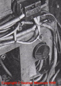
The above photo is German and shows an experimental vehicle under modification, as seen from the engine compartment. Most of the seals are gone but you can see half of a duct arm still dangling in its hole. (This vehicle may have had more cables than a normal one.)

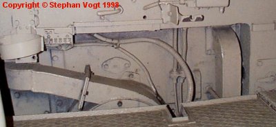
Another view of the "APG" tank. The rectangular opening at bottom left of the photo has an access panel fixed to it, and this panel can apparently be removed without disturbing anything else. The rectangular opening at the right side of the cubby is more problematic; since the flow of air in the circular duct is anticlockwise in the photo, the duct arm on this side must go vertically up and so it obstructs the area. But a handwheel is located just behind the firewall here, and it controls the engine's water cooling system. Access to the handwheel is necessary, despite the duct.
Therefore this duct arm and panel are fixed together and can be removed as a unit. The panel has no bolts, it simply clips into the rectangular hole; it has a handle for easy removal, as you can see; and the duct can be disconnected from the circular housing by loosening four wingnuts on a flange at its base (not visible here due to the floor panels).
Several cables pass through this area. It's interesting that the rearmost floor panel has a cutout just here; this allows a thin vertical rod (missing from this vehicle) to pass down from the handle just above the opening, to a valve on the air duct on the floor. In the photos of the Saumur vehicle on this site, the rear floor panel is upside down and so the cutout is misplaced. Also, note that this floor panel has a lip at the back edge to prevent items rolling off it; no other edge of any floor panel has such a lip.
The diagram above shows the heavy retaining door bolted into the firewall. This door is made of 8mm steel plates, including 3 long welded pieces that carry its bolt holes; the main body of the door is flush with the surrounding recess wall. As you can see, a complete ring of 12 evenly spaced bolt holes is formed when this door is installed. These are for the mounting bolts that hold the front of the engine in place. There is also a small lozenge-shaped panel; this gives access to an adjustment on the engine's flywheel housing. You can purchase a photo of this panel installed in the firewall of the renovated Tiger, from Bovington Museum.
The diagram above shows the shape of the duct arms. They extend from a cylindrical housing, 400mm wide and 80mm deep; behind it is a larger cylinder, 440mm wide and 50mm deep. Note that the combined depth is 130mm, the same as the depth of the recess; so the floor panels can abut to the front of this housing (see the photos earlier), and no space is wasted.
Note also that the arm on the right-hand side of the diagram is not centered in its panel. In fact, a notch is cut in the wall to allow it to pass very close to the outside edge. This has the appearance of a 'hack' or change to the original design, and I suspect that the corresponding exhaust pipe on the HL210 was moved upwards and outwards at a late stage, making this change necessary. Note also that the opening in the main firewall panel is wider on this side, which again looks like a change to make extra room; also, this duct arm has two flanges at its base, 50mm apart, and the second one seems to have no function; it may be a spacer that puts the duct in its new position.
[1] Survey of Tiger 250031, by Stephan Vogt
[2] Survey of Tiger 250122, at Bovington museum, by David Byrden


