The Tiger 1 had a water-cooled engine. There were two radiators, one in each rear sponson. Attached to the back face of each radiator was a large, hollow, curved duct guiding the air up to a pair of fans. Above the fans, in the top deck, were armoured grilles. This layout was first drawn up in a 1941 Tiger design drawing, made when the sponsons were added to the hull. It's inefficient because the ducts are in effect wasted space that needs armour protection, adding to the size and weight of the Tiger.
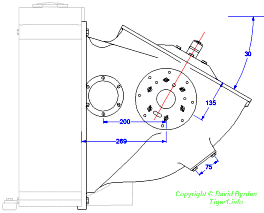
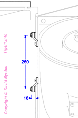
This diagram shows a side view of an air duct attached to a radiator. The water pipes are not shown; the input pipe passed above the duct, and the connector for the exit pipe can be seen under the duct. On the side of the duct there is a small hole that draws hot air directly from the engine room, and a large flat surface with numerous bolt holes.
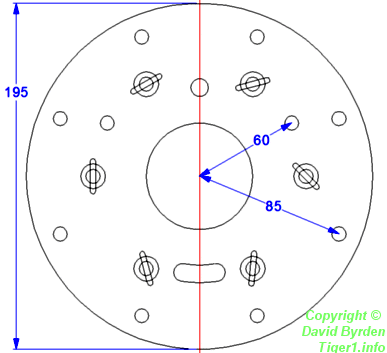
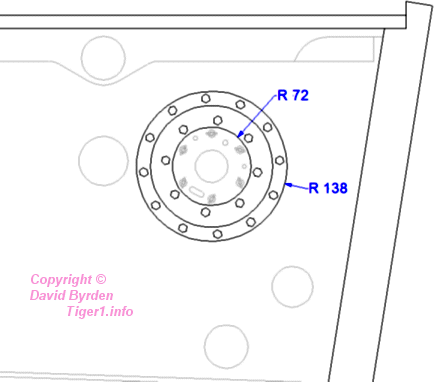
This diagram shows the pattern of bolt holes. It is rotated 30 degrees; refer to the first diagram.
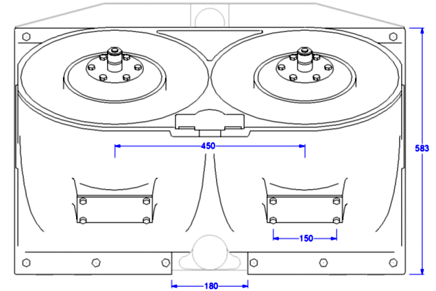
This diagram shows a duct from behind. The ducts seem to be white-metal castings. They were symmetric and could be installed in either side of the Tiger.
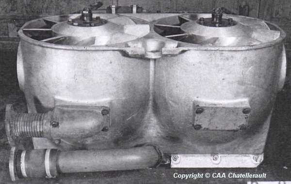
This photo shows a fan duct configured for the right-hand side of a Tiger. At the bottom of the photo is a rigid pipe for carrying water out of the radiator. Above it is a short flexible metal pipe by which the fan draws hot air from the engine's exhaust-pipe shrouds. The radiator's water inlet pipe can be glimpsed at the top of the photo.
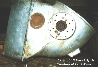
The unused openings in the duct (i.e. those on the outer side of the vehicle) were sealed with metal plates.
Each radiator and its duct were bolted together. The unit was insulated from mechanical shock. It stood on six rubber feet; four at the front of the radiator, and two at the back of the duct.
A drive shaft from the engine compartment passed through the side of the duct. Since the sponsons were floodable, this joint had to be waterproof as well as shockproof.
A flat ring made of 8mm rubber was fixed to the inside wall of the engine room [2] by a ring of 12 bolts (at 125mm radius). It was also bolted to the flat face of the duct by 8 bolts (at 85mm radius). The drive shaft passed through additional seals in the middle of this ring.
[1] Survey of Tiger 250122, at Bovington museum, by David Byrden