About this detail of the Tiger
The exhaust pipes of the Tiger's engine were extremely hot and had their own dedicated cooling air flow. Each exhaust pipe was wrapped in a sheet-metal shroud and cold air was forced along it.
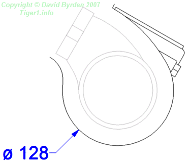
The exhaust pipes had a 90mm external diameter, and the shrouds had about a 128mm diameter. This is a cross-section through both.
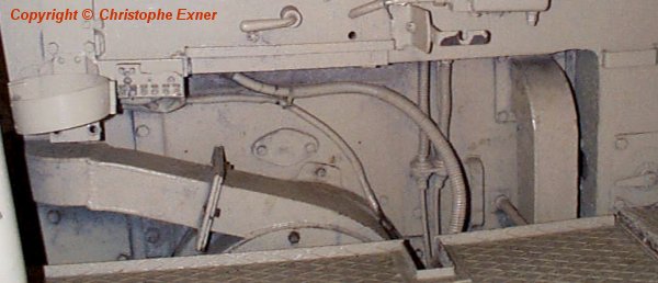
The cold air was driven by a fan mounted on the front of the engine itself [3] . The fan was in the crew compartment, embedded in the firewall. This photo of a museum Tiger [4] shows the firewall; you can see the top of the fan housing and the ducts that take air to the engine's two exhaust shrouds. The ducts have a rectangular cross-section.
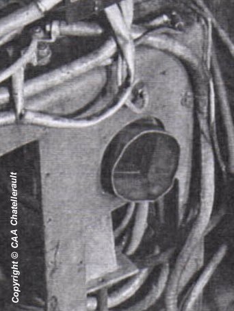
Seen from the other side of the firewall, this is the right-hand duct [5] dismounted from the wall and hanging loose in its hole. We can see that it changes from rectangular to round cross-section in order to mate with the shroud.

The shrouds for the exhaust pipes were fixed to the engine. They were each made of two parts. This is the lower part of the right-hand shroud [6] .

The shrouds for the HL 230 engine were slightly different to those of the HL 210. A port was added to the top of each shroud. In the Tiger B and Panther tanks, the hot air exited through this port; while in the Tiger E, the port was sealed by a cap.
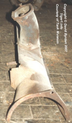
This shroud is from the Bovington Museum collection and apparently belongs to a Tiger B. The outlet tube would not be present in a Tiger E.
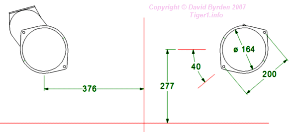
The rear of each shroud had bolt holes. We have the German specifications [7] for them, shown here.
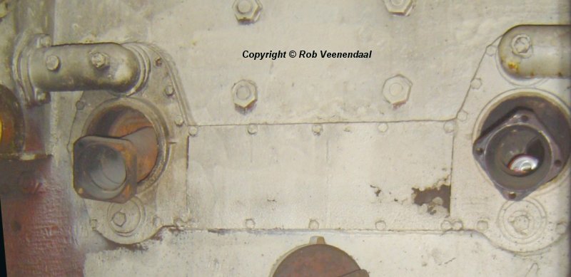
In the Tiger E, a short flexible pipe took the air from the rear of each shroud to a large duct on the rear wall of the tank [3] . I can find no photographs of these pipes. This is the rear wall of a Sturmtiger [2] .
[1] Workshop drawing 021 B 425 B1 : HL 230 external dimensions
[2] Survey of Sturmtiger at Panzermuseum Munster, by Rob Veenendaal
[4] Survey of Tiger 250031, by Stephan Vogt
[5] German report on experimental ventilation gear for Tiger 1, now at Chatellerault archive
[6] Survey of Tiger 250122, at Bovington museum, by David Byrden
[7] Workshop drawing 021 B 425 B1 : HL 230 external dimensions