About this detail of the Tiger
The Tiger's engine (the HL 210 P45 and later the HL 230 P45) had two banks of 6 cylinders. Exhaust gases from each bank were collected by a manifold pipe.
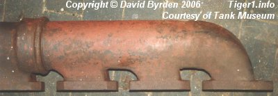
This is the right-hand exhaust manifold from a HL 230 P30 (from the Tiger B at Bovington) [1] , in its original colours. The P45 units were identical.
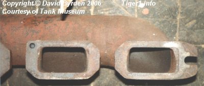
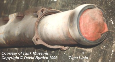
This is the forward section; there is a solid ring fixed at the end. This ring is made of heat-resistant material and has a spherical outer surface. Further along, a flange is loosely threaded on the exhaust pipe: the inner surface of this flange fits the spherical ring exactly.
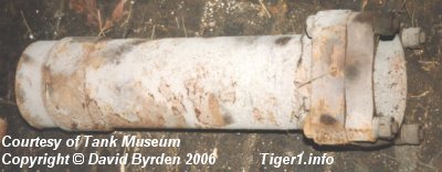
This is the rear section of an exhaust pipe. One end of it is shaped similar to the flange mentioned above. A flange can be attached by 4 bolts, as shown here. The spherical ring is missing from this section of pipe. It was carried on the thick sleeve near the end. It could slide along this sleeve to accomodate lengthwise variations in the engine's position.
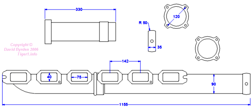
By bolting a flange to the rear section, one could trap the ring and form a seal against exhaust gases. When the bolts were tightened up, the joint was not flexible. These are the parts of the right-hand exhaust pipe.
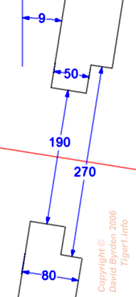
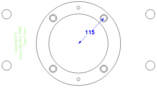
The 80mm rear armour plate of the Tiger had two holes, one for each exhaust pipe. The dimensions of a hole are shown here.
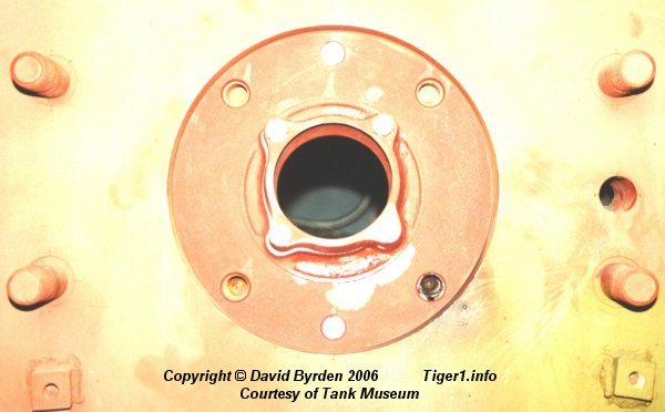
Each hole was sealed by a disc, held in place by two screws. I assume that the hidden side of this disc carried a rubber ring to form a waterproof seal. This rubber ring would be located near the outer edge of the disc, so that the heat of the exhaust pipe would not damage it.
The screws holding the disc (top and bottom) had flat heads. So, the surface of this disc was flat. I assume that when the external exhaust stacks were bolted to this hole, the visible side of the disc pressed against another rubber ring to form another waterproof seal.
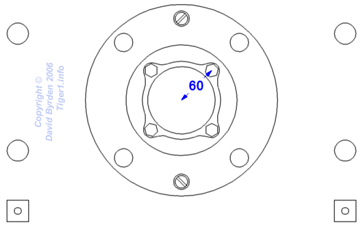
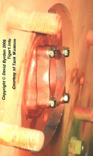
The disc was a casting that incorporated the rearmost universal joint for the exhaust pipe. Notice that the flange in the disc was vertical, but the disc itself was angled at 9 degrees to conform to the rear plate of the hull.
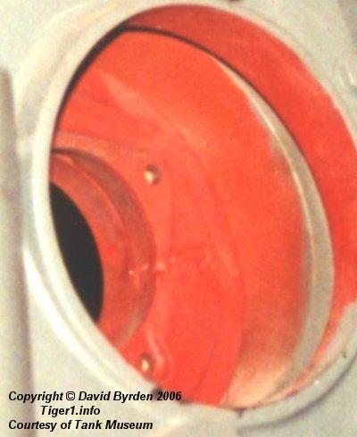
This shows the disc as seen from the inside of the tank. (The colours are not original.)
[1] Survey of Tiger 250122, at Bovington museum, by David Byrden
[3] Workshop drawing 021 B 425 B1 : HL 230 external dimensions