About this detail of the Tiger
Dragon's kit provides a hull MG that can move freely in both axes, and has interior detail. The dust cover and the underwater sealing cover are both included. However, there are a couple of items missing from the interior.
The whole assembly is highly accurate for the most part; even the ball has the correct radius. But on the rear face of the superstructure armour plate, accuracy is sacrificed to allow motion.
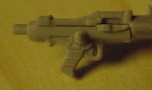
Start by assembling the upper and lower halves of the MG (J27 and J28). These are VERY finely molded and are intended to fit together precisely. Unfortunately, the plastic molding technology is not quite good enough for what has been attempted, and I had to sand away a little from the front of J27 and the back of J28 to achieve a perfect fit.
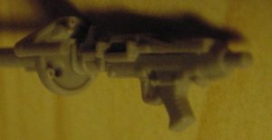
Now, slide J20 along from the front for a dry-fit. Again there is a problem; above the hole in J20 is a very tiny raised line that can prevent the flange on the gun from butting up to give you a strong joint. Scrape away at this tiny ledge from below. Use the handle of the MG as your vertical when rotating J20 into alignment; the pole on J20 should be very slightly above the level of the gun barrel.

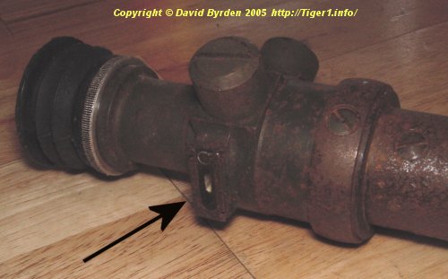
J20 represents a mounting frame on the rear of the ball; the real frame (pictured above ) doesn't look much like J20, and it isn't located so far back. But this inaccuracy does not affect the other parts of the assembly; the gun, head pad etc. are all at their correct positions relative to the ball.
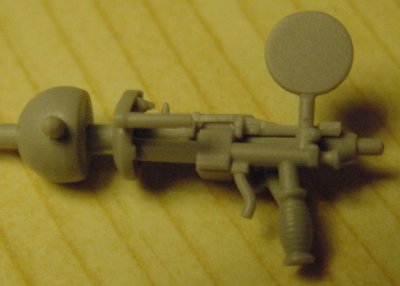
Part J26 includes the gunner's handle and head pad. It attaches to J20 and the underside of the MG. I found that it would not line up straight unless the attachment to the MG was sanded down.
There's a more serious problem with J26; it is misplaced. It is very close to the gun, and this is correct (the true distance was 70mm) but it's about a millimeter too high. That's a significant distance on this tiny unit!
The part carries the gunner's head pad, on a rod which you are supposed to bend. (I wonder if the plastic will straighten itself as the years pass?) The real rod had a gentle curve, so it comes out looking correct; but Dragon have made the rod short, to compensate for the putting J26 too high.
Part J25 is an ammunition sack which you are supposed to attach below the MG. I don't yet know how these sacks were attached, but I'm sure it would have not have had its lid closed like this part depicts.
The assembly is missing the forehead pad and telescope. The pad was removable, and was mounted on a thin pole (which is represented on J20) so this might not worry you. But the telescope was unlikely to be taken out from the gun near a combat zone.
Most German tanks of the period used the same telescope for their hull MG position. It was called KzF2 and this is an example.
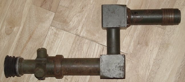
The telescope has a staggered shape so that the gunner's line of sight can be brought closer to the MG than his head would normally allow.
This example is finished in dark green (perhaps Feldgrau?) and as far as I know it is typical of late-war construction, having a heavy cast body. For the tank represented in the Dragon kit, an early war example would be appropriate. It had a very similar shape, and the same dimensions, but the body was a thin shell painted black. Bovington Museum seem to have one of this kind in their early Tiger.
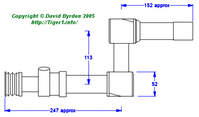
This sketch shows the basic dimensions of the KzF2.
The position of the telescope relative to the MG depends on the construction of the ball mount. For the mount in the Tiger 1, the precise relationship is shown in this next diagram. It shows a rear view of the ball with the KzF2 still installed. Note that the scope is tilted so that the gunner's eye is slightly below the MG.
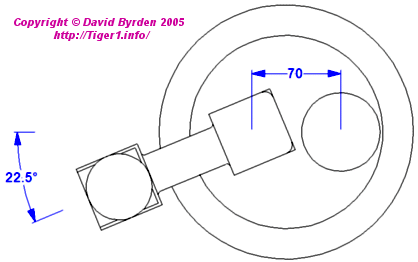
The telescope is designed to be tilted at exactly this angle of 22.5 degrees (which is one sixteenth of a circle). In fact, when it is installed, the adjustment screws are exactly vertical and horizontal.
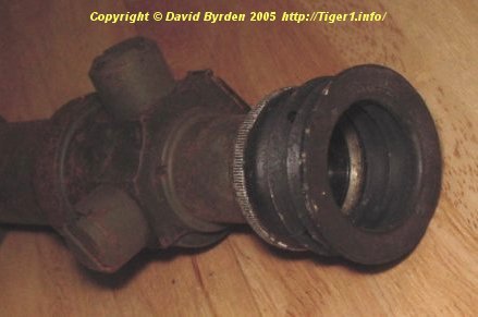
As the next picture shows, there is a small glass window on the body of the telescope. With the unit installed at the correct angle, this window is on the left, angled slightly downward. A custom light fitting can be clipped onto this window; the fitting contains a bulb to illuminate the graticule at night. This implies that a free electric lead with the small fitting at the end would be located near the radio operator.
This next diagram, after the Spielberger book, shows the relation of the telescope, gun and handle in the mount. The telescope is indicated as [1]. The handle (part J26) is drawn in heavier ink; it is about 83mm below the gun axis, which translates to 2.3mm on the model.
Notice the small supporting arm [2] which supports one of the solid cubes of the telescope. The eyepiece is about 174 mm to the left of the gun axis. It aligns with the gunner's right eye, so it is towards the right side of the head pad.
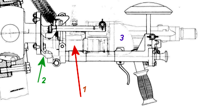
The diagram shows the forehead cushion [3] which is absent from the kit.