About this detail of the Tiger
In the original design of the Tiger's suspension, four wheels per side were placed between the guide teeth of the tracks. These wheels, and only these wheels, carried 2 tyres.
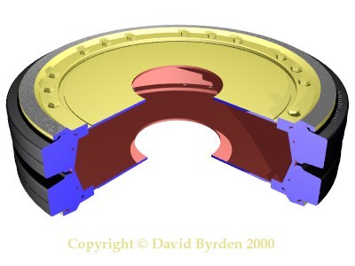
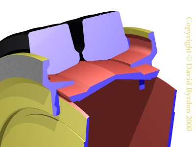
These models show the overall structure of one of these wheels.
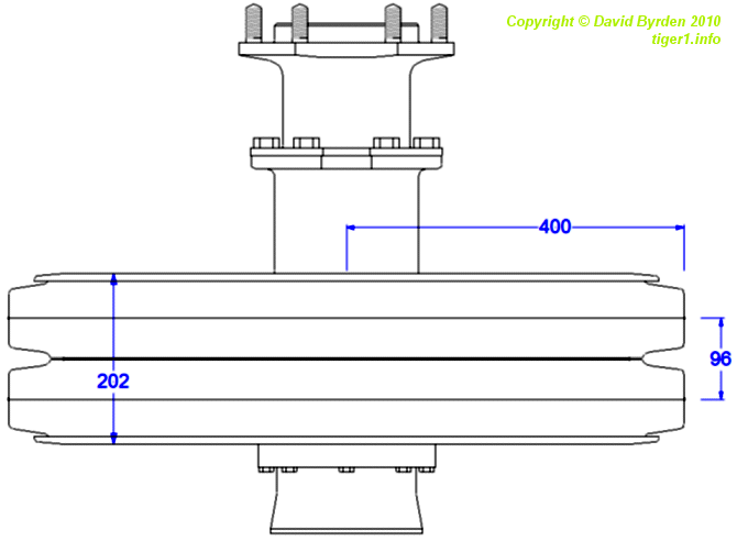
This profile shows a wheel and the hub that carried it. The outer end of the hub carried another wheel with a single tyre. The outer wheel, and a portion of the hub, could be removed to bring the tank within railway guage.
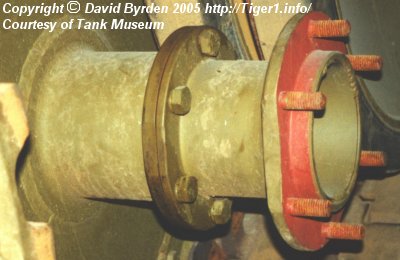
This photo shows the joint where the hub could be broken (the colours are not original).
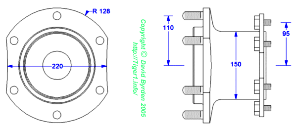
This diagram shows the removable part of the hub. The sides of the flange are cut away slightly to help with the removal of adjacent inner wheels, which would not clear the flange unless the ground were perfectly level.
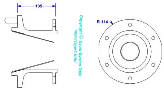
This diagram shows a cross-section of the removable part. A thin cone was welded inside it.
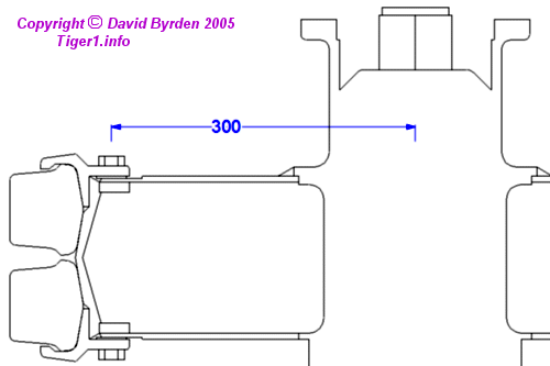
This profile of the wheel shows that the hub had a large cap screwed into it. This cap covered the oil reservoir for the axle. There was a hexagonal pipe on this cap.
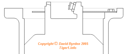
The pipe had a hollow end, and within it there was an oil-filling tap.
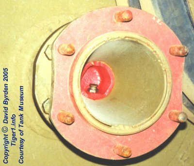
This photo of the Bovington vehicle shows how the oil-filling tap was accessible through the cone in the removable part of the hub.
Crews sometimes operated their Tigers with the first outer road wheel removed, because it tended to scoop mud into the suspension area. When the tank was configured for transport, all of the outer wheels were removed. In each case the outer portion of this hub was removed, exposing the flange at the joint.
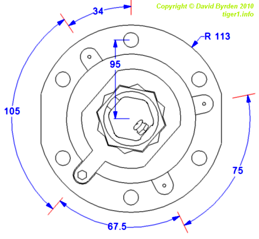
This diagram shows the exposed flange. To prevent the cap of the oil reservoir from working loose, a sheet-metal locking ring was screwed into the flange.
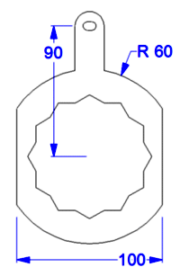
The ring (shown above) could be threaded onto the hexagonal pipe at intervals of 30 degrees. There were four locating holes in the flange, carefully positioned to divide these intervals into four. The locking ring therefore needed only 3.75 degrees of slack in either direction so that it could always be locked into one of these holes.
[1] Survey of Tiger 250122, at Bovington museum, by David Byrden