About this detail of the Tiger
The crankshaft of the Tiger's engine was held securely in roller bearings, but of course it was free to rotate. There was a danger of torsional vibrations.
The front end of the crankshaft was attached to a massive flywheel [2] . Twisting of the crankshaft therefore manifested at the rear end. A vibration damper was attached there.
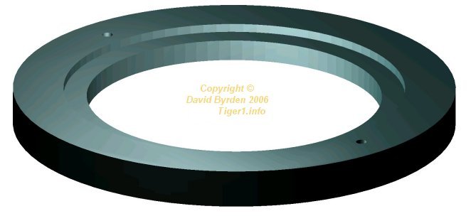
The damper had its own flywheel, as shown above.

The dimensions of the flywheel are given here.
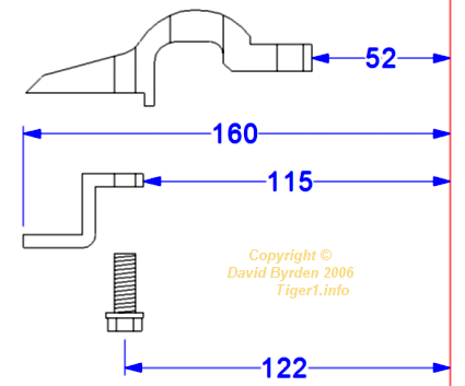
This flywheel was not firmly attached to the crankshaft: instead it was pressed between two rings. A section of the two rings is shown above. The outer disc had holes in it, giving access to bolts on the crankshaft.
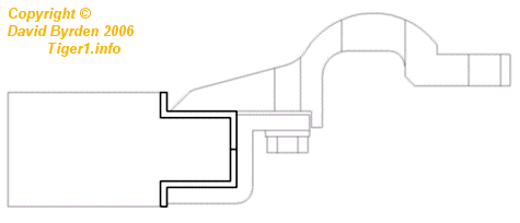
Where the discs met the flywheel, there were thin friction rings made of fiber [2, see page 166] . A section of the assembled unit is shown here. The friction rings wrap the inner flange of the flywheel.
The damper operated like so: the flywheel, being massive, tended to rotate at a constant rate. When the crankshaft twisted relative to the flywheel (due to vibrations), the friction rings would damp the motion.
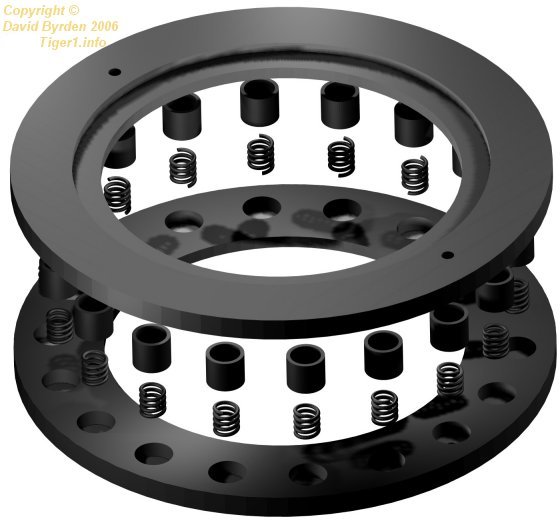
To ensure the correct pressure on the friction pads, the flywheel was divided in two [2, see page 155] . Eighteen springs were pressed between the two discs, forcing the flywheel halves against the friction rings with a known force.
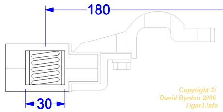
The springs are shown in this diagram. Each spring had a protective sleeve.
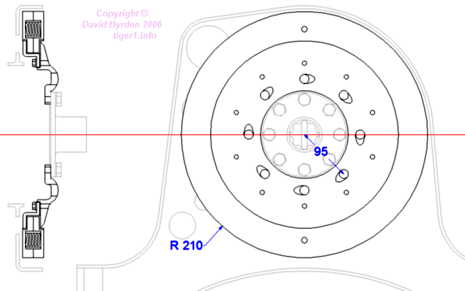
The flywheel was situated in the engine's rear support frame. In HL 230 engines, the power take-off shaft was bolted to the outside of the flywheel as shown here. On HL 210 engines, a thin flat plate blanked off the central hole.
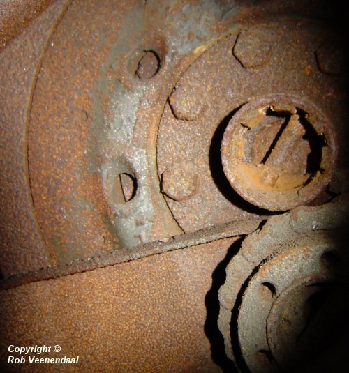
This is the flywheel on the Tiger E in Saumur museum [4] . At top right you can see the power take-off shaft. To the left you can see the flywheel's outer cover with its holes. At extreme left is the surface of the flywheel itself.
The holes in the outer cover ring seem to be shaped so as to scoop air. The flywheel rotates counterclockwise as seen in this photo, so they would expel air from the cavity behind the flywheel.
[1] Workshop drawing 021 B 425 B1 : HL 230 external dimensions
[3] German assembly manual for HL 230 engines
[4] Survey of Tiger 251114, at Panzermuseum Munster, by Rob Veenendaal