About this detail of the Tiger
The Tiger's main gun (the KwK36) was equipped with a Clinometer. This is a device that measures angles; in this case, the angle of elevation of the gun.
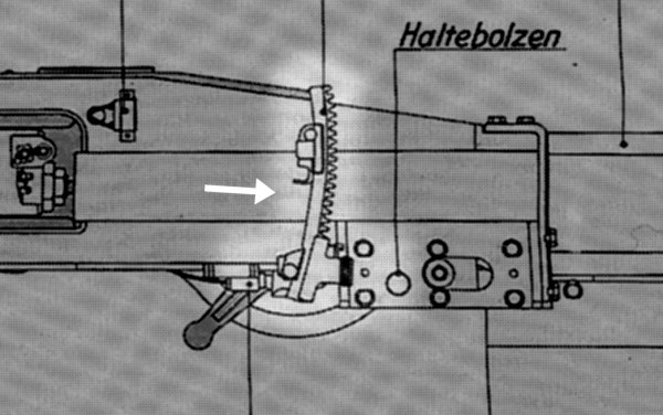
A diagram of the KwK36 was drawn early in the Tiger's design phase. This is part of the diagram. It shows the clinometer (indicated by an arrow), attached to the left side of the gun's cradle.
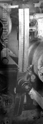
This is the clinometer found in the Bovington Museum Tiger "131" upon capture. It's not exactly the same as drawn in the diagram; it extends further down, allowing it to measure depression as well as elevation. We don't know if the shorter version of the clinometer was ever manufactured.
The device consists of a graduated metal arc bearing a sliding indicator that can be locked in place. The indicator is a spirit level, with a bubble and an illuminating bulb. The gunner would slide it along the curved arc until the bubble indicated that it was level; then he would read the gun's angle off the arc.
The British evaluation of Tiger "131" states that this clinometer was graduated on its left side in mils, from -100 to 400. Black ink was used above and red below. Part of its right side was graduated with a range scale running from 0 to 80. The maximum 80 (hundred meters) was at 151 mils elevation.
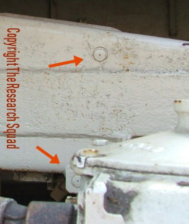
The clinometer was fixed to two posts on the gun's cradle. These posts could retract into the cradle if the clinometer was not present. In fact the lower one was spring-loaded and would retract itself. This photo shows Tiger "712", a very early Tiger in a museum. Its two posts are indicated; both are withdrawn into the cradle.
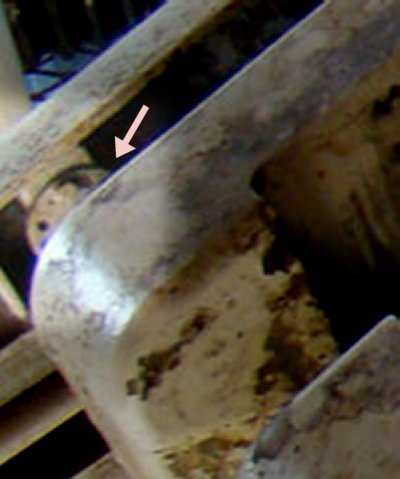
The clinometer could be adjusted. The adjustment mechanism was on the upper supporting post, on the inner side of the gun cradle, as indicated here. Unfortunately I don't have a better photo of the mechanism in Tiger "712".
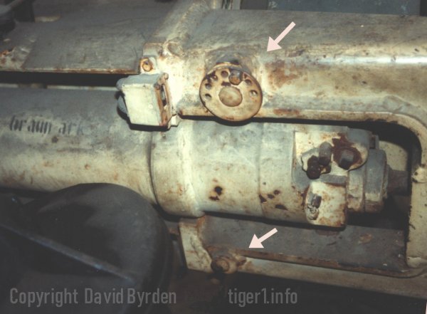
At some time (we don't know exactly when) the gun's design was altered, moving the clinometer forward to where the gunner could more easily read it. This photo of Tiger "131" in a museum shows its clinometer posts. Again, the clinometer is missing and the posts are retracted. The adjustment mechanism is the same but now it is on the outside.
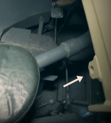
When this desgn change was made, there was a stockpile of gun cradles already built to the old specification. The new fixtures were simply added to them. The cradle in Tiger "131" therefore retains the unused sleeve for the lower post.
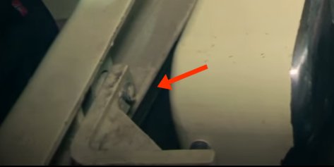
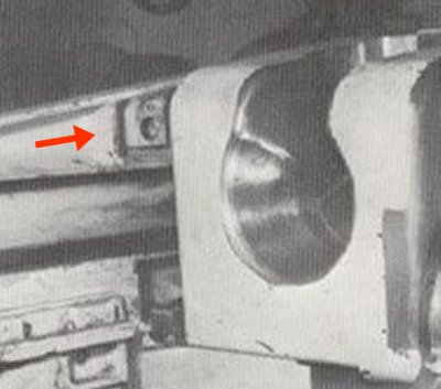
This tank "131" also has the original hole for the upper post. A recoil stopper is now bolted into the hole. But as the WW2 photo shows, the stopper is not an original part. Both holes were empty when the tank was captured and surveyed in 1943.
The "mid" Tiger at Kubinka museum was built much later. Its clinometer was in the new position. Unlike Tiger "131", it has no remnants of the old position.
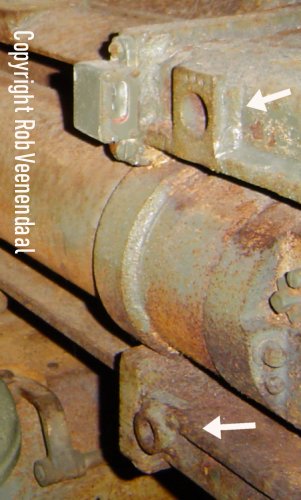
It is probable that the clinometer was dropped from the Tiger's design, perhaps as soon as late 1943, but we don't have a documentary record of this. We have only the final-version Tiger in Saumur, shown here. The posts are missing, almost certainly because they were never installed. But in typical German fashion, the factory drawings were not carefully purged of all the relevant details. And so this gun cradle still has the welded housings for the posts, indicated in this photo.
The calibration mechanism is worth discussing because the British experts who analysed Tiger "131" failed to understand it completely. The clinometer was calibrated by twisting its upper support post. This would rotate the clinometer around the lower support post, which acted as a hinge.
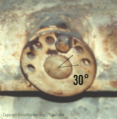
The upper post was keyed into a sleeve with a disc at the end. The edge of the disc was knurled, and the gunner would calibrate the clinometer by turning the disc. When satisfied, he would lock the disc with a single bolt. According to the British report, the post was off-center in the sleeve ("eccentric") and this is why its rotation moved the clinometer.
As you can see here, there were seven holes for the bolt, spaced thirty degrees apart. The holes were larger than the shank of the bolt, so that the disc could be turned at least ten degrees without removing the bolt.
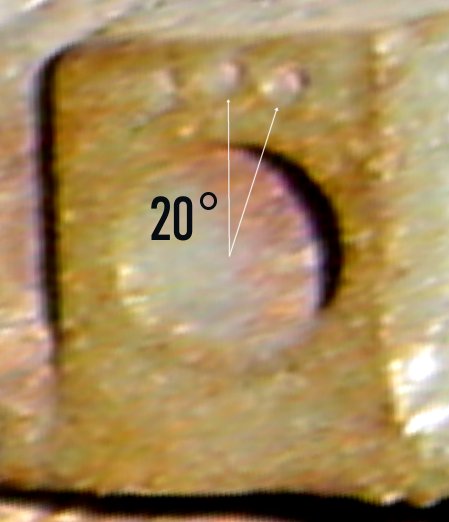
The disc and sleeve fit snugly into this welded mount on the cradle. It had three bolt holes, twenty degrees apart. Therefore the disc could be turned continuously through an arc of 190 degrees with at least one of these bolt holes always usable.
According to the British evaluation, each hole on the disc corresponded to about 1 milliradian of tilt for the clinometer. Therefore the total calibration range was about 6 mils, or one third of a degree.