About this detail of the Tiger
The Tiger 1 was designed with a hydraulic system to open the grilles over the cooling fans [3] . It was felt that the airflow through the closed grilles would sometimes be insufficient.
The system was dropped after the demonstration of the first complete vehicle [3] . Thereafter, the grilles could be opened only by hand.
I am not aware of any photographs or drawings of the hydraulic system, but I will try to reconstruct it from the remaining evidence.
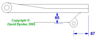
There is a surviving German diagram [1] that shows a loop under the rear edge of the grille. From that diagram I have made this drawing with estimated dimensions.
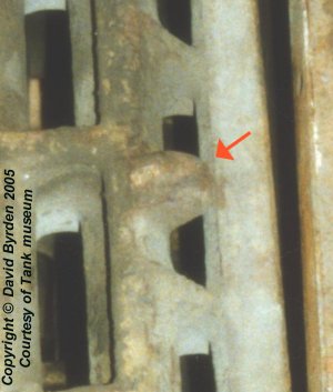
Although it is hull #122, the Bovington vehicle still has the loop under its grilles [2] . It was common for features of the tank to remain, especialy on castings, after they were supposedly deleted. The loop is under the middle of the rear edge. Notice that the makers have not drilled the hole in the loop.
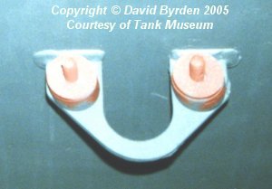
The compartment under the grille contained an air duct with two fans. A support for this duct was welded to the rear wall. It is interesting that a U-shaped hole is provided in the middle of the support. The fan duct has a corresponding hole in it. The hole apparently remained in place throughout the production run; but it was sealed by the blanking plate over the fans.
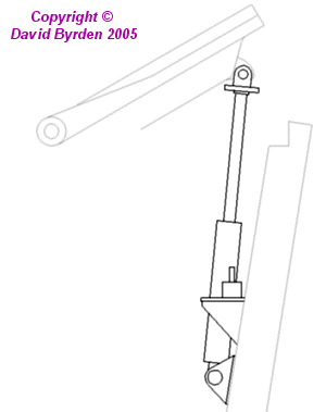
This all suggests that the system comprised a hydraulic cylinder on the inside rear wall of each fan compartment, passing through this hole. The top end of the cylinder - or, more likely, the moving arm - would have been linked to the grille at the loop.
To follow the motion of the grille, the cylinder would have to swing slightly back and forwards. The U-shaped hole allows this. The width of the hole, 55mm, is much wider than needed for a hydraulic arm; therefore I assume that the cylinder itself was threaded through this hole. This suggests that it was about 50mm in diameter.
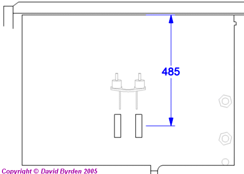
Another piece of the puzzle appears in the book "Tiger I and II: combat tactics" [4] . A photograph of the inside rear wall of a very early Tiger shows two metal strips under the fan mount. This drawing of the right-hand compartment wall gives their approximate position. They can only be part of the hinge for the hydraulic cylinder.
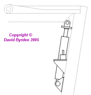
Using these clues, and with reference to the hydraulic shock absorbers in the Tiger's hull, I have made these speculative drawings of a hydraulic cylinder for the Tiger's rear grilles.
[1] German sketch SK3426: engine upgrade
[2] Survey of Tiger 250122, at Bovington museum, by David Byrden
[3] DW to Tiger 1
[4] "Tiger I & II; combat tactics", Tom Jentz, Schiffer Military publications